Tracked Mobile Robot Suspension System
A mobile robot and suspension system technology, applied in tracked vehicles, motor vehicles, transportation and packaging, etc., can solve the problems of small contact area, unsatisfactory buffering and vibration absorption effect, etc., and achieve the effect of buffering and absorbing vibration energy and compact structure
- Summary
- Abstract
- Description
- Claims
- Application Information
AI Technical Summary
Problems solved by technology
Method used
Image


Examples
specific Embodiment approach 1
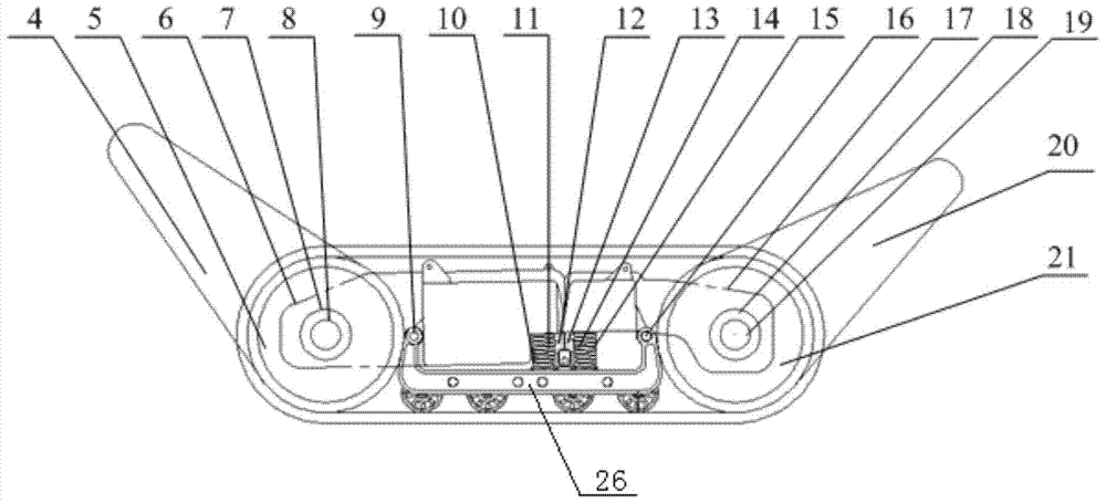
[0013] Specific implementation mode one: the following combination figure 1 and figure 2 Describe this embodiment, the crawler type mobile robot suspension system described in this embodiment, it comprises front swing arm and front driven wheel suspension 1, rear swing arm and rear drive wheel suspension 2 and middle small road wheel suspension 3; The front swing arm and front driven wheel suspension 1 and the rear swing arm and rear driving wheel suspension 2 are connected by crawler transmission, and the middle small road wheel suspension 3 includes two sets of load systems and U-shaped frames 26; two sets of load systems The front and back are arranged side by side, and a U-shaped frame 26 is arranged on the top of the two groups of load-bearing systems. The floating connection between the driving wheel suspension 2.
[0014] Each unit acts as an independent entity connected to the small road wheel system through floating connections. Through modular design and integrat...
specific Embodiment approach 2
[0015] Specific implementation mode two: the following combination image 3 Illustrate this embodiment, this embodiment will further explain Embodiment 1, the front swing arm and the front driven wheel suspension part are composed of two front driven wheels 5, two front swing arms 4, two front spring damping systems 11, front floating Composed of connecting shaft 9, front swing arm drive motor and its deceleration mechanism;
[0016] Two front driven wheels 5 are coaxially arranged side by side, each front driven wheel 5 is connected to a front swing arm 4, and the swing arm action of the front swing arm 4 is driven by the front swing arm drive motor and Its deceleration mechanism controls; Front box body 6 forms floating connection with front spring damping system 11 by front floating connecting shaft 9, and front floating connecting shaft 9 is fixed on the front U-shaped top of U-shaped frame 26.
[0017] The front spring damping system 11 is composed of the front short spr...
specific Embodiment approach 3
[0020] Specific implementation mode three: the following combination image 3 Describe this embodiment, this embodiment will further explain Embodiment 1, the rear swing arm and the rear drive wheel suspension part include two rear drive wheels 21, two rear swing arms 20, two rear spring damping systems 14, rear floating connecting shaft 16;
[0021] Two rear drive wheels 21 are coaxially arranged side by side, each rear drive wheel 21 is connected to a rear swing arm 20, and the swing arm action of the rear swing arm 20 is driven by the rear swing arm drive motor and Its deceleration mechanism controls; Rear casing 17 forms floating connection with rear spring damping system 14 by rear floating connecting shaft 16, and rear floating connecting shaft 16 is fixed on the rear U-shaped top of U-shaped frame 26.
[0022] The rear spring damping system 14 is composed of a rear short spring and a rear rubber damping material 15. The rear rubber damping material 15 is filled in the ...
PUM
 Abstract
Description
Claims
Application Information
 - R&D
- Intellectual Property
- Life Sciences
- Materials
- Tech Scout
- Unparalleled Data Quality
- Higher Quality Content
- 60% Fewer Hallucinations
Browse by: Latest US Patents, China's latest patents, Technical Efficacy Thesaurus, Application Domain, Technology Topic, Popular Technical Reports.
© 2025 PatSnap. All rights reserved.Legal|Privacy policy|Modern Slavery Act Transparency Statement|Sitemap|About US| Contact US: help@patsnap.com