
Ventilation unit using temperature and atmospheric pressure equilibrium and preservation system using same

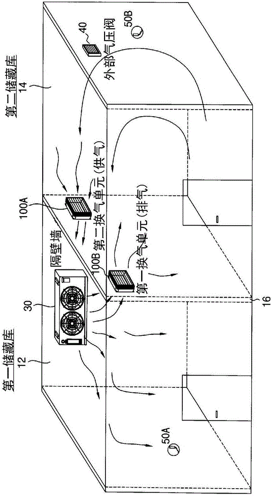
A technology of air pressure balance and air exchange port, which is applied in the field of storage system and can solve the problems of increased power consumption, rising, shock absorber and pipeline size increase, etc.

Inactive Publication Date: 2015-12-02
沈棋燮
View PDF7 Cites 6 Cited by
  • Summary
  • Abstract
  • Description
  • Claims
  • Application Information

AI Technical Summary

Problems solved by technology

However, in large-scale industrial or commercial walk-in coolers (WORK-INCOOLER) or freezer refrigerators, there are the following problems: the fan of the freezer evaporator, the shock absorber used to connect the freezer and the refrigerator And the size of the pipe becomes larger, the resulting heat loss and the icing of the shock absorber, and the air pressure in the refrigerator room rises and the air pressure in the freezer room drops when the air in the freezer room is blown to the refrigerator room, resulting in inability to for smooth air circulation
[0003] In addition, in order to relieve the negative pressure caused by the temperature drop of the freezer, an air pressure valve is usually installed, and the outside air passing through the air pressure valve flows into the freezer to cause heat loss in the freezer, and the air in the freezer with a higher air pressure passes through. The air pressure valve installed in the refrigerator room leaks to the outside, causing heat loss, material costs, labor costs, and power consumption. Although the cost and labor costs increase, when the capacity of the freezer room increases, it is necessary to install them separately in the refrigerator room. Freezer, or even if one condensing unit is used, separate coolers for the freezer and refrigerator, and connect the freezers with refrigerant piping

Method used


Image

  • Ventilation unit using temperature and atmospheric pressure equilibrium and preservation system using same
  • Ventilation unit using temperature and atmospheric pressure equilibrium and preservation system using same
  • Ventilation unit using temperature and atmospheric pressure equilibrium and preservation system using same

Examples


Embodiment Construction

[0075] The specific structures and functional descriptions of the embodiments of the present invention disclosed in this description are only shown for illustrating the embodiments of the present invention, and the embodiments of the present invention can be implemented in various forms, and are not limited to the embodiments described in this description. the described embodiment.

[0076] While the invention may be modified in many ways and be embodied in a variety of forms, specific embodiments are illustrated in the drawings and described in detail in the specification. However, the present invention is not limited to the specific disclosed form, and all modifications, equivalents, and replacements included within the spirit and technical scope of the present invention are included in the present invention.

[0077] Terms such as first and second can be used to describe various structural components, but the structural components are not limited to the terms. The terms ar...


PUM


Abstract

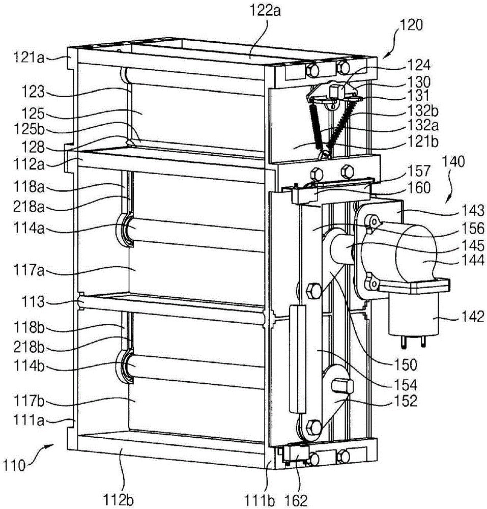
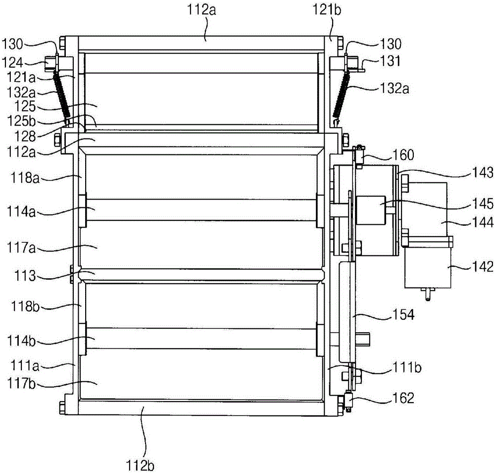
The present invention relates to a ventilation unit using equilibrium of temperature and pressure, and a storage system using the same, and more specifically, to a pressure equilibrium ventilation unit to control the temperature of a closely located place using heating source or cooling source generated from one heating device or cooling device, and to a storage system using the same. According to an embodiment of the present invention, the pressure equilibrium ventilation unit comprises: a first frame assembly having a first frame and a first opening and closing plate; a second frame assembly having a second frame and a second opening and closing plate; a driving part having a forward and reverse motor; and a lock control part which maintains a second ventilation unit in a closed condition when a first rotation axis opens a first ventilation unit as rotated by the preset angle according to an opening signal.

Description

technical field [0001] The present invention relates to a ventilation unit using temperature balance and air pressure balance and a storage system using the ventilation unit. More specifically, it relates to controlling the temperature of an adjacent place by using a heat source or a cold source generated by a heating device or a cooling device The air pressure balance ventilation unit and the storage system using the air pressure balance ventilation unit. Background technique [0002] In the household refrigerator, the temperature of the refrigerator compartment can be adjusted by using the evaporator of the freezer compartment without providing a separate evaporator in the refrigerator compartment. However, in large-scale industrial or commercial walk-in coolers (WORK-INCOOLER) or freezer refrigerators, there are the following problems: the fan of the freezer evaporator, the shock absorber used to connect the freezer and the refrigerator And the size of the pipe becomes l...

Claims


Application Information

Patent Timeline
Patent Type & Authority Applications(China)
IPC IPC(8): F24F7/00F24F7/10F24F11/02F25B29/00F24F11/76
CPCF24F2011/0002F24F2013/148F25D17/005F25D17/047F25D2700/12F25D2700/122F24F11/75F24F11/76F24F11/89
Inventor 沈棋燮
Owner 沈棋燮
Learn More