
Valve device for a motor vehicle

A technology for valve devices and motor vehicles, which is applied to valve devices, machines/engines, valve lifts, etc. It can solve the problem of high cost and achieve the effect of low cost and reliable closure

Inactive Publication Date: 2015-12-02
CONTINENTAL AUTOMOTIVE GMBH
View PDF6 Cites 1 Cited by
  • Summary
  • Abstract
  • Description
  • Claims
  • Application Information

AI Technical Summary

Problems solved by technology

The disadvantage of this valve arrangement is the cost-prohibitive housing design due to the coolant channels with the connections connected thereto

Method used


Image

  • Valve device for a motor vehicle
  • Valve device for a motor vehicle
  • Valve device for a motor vehicle

Examples


Embodiment Construction

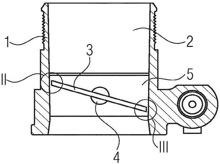
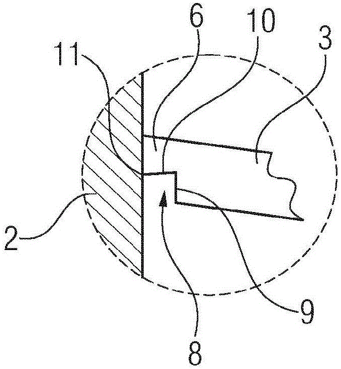
[0018] figure 1 Shown as a valve arrangement is a throttle valve of the pipe-joint type with a housing 1 and a flow channel 2 in said housing, in which a disc-shaped flap 3 is arranged . The valve flap 3 is fixedly connected to a shaft 4 , which is rotatably mounted in the housing 1 . The shaft 4 is driven by a motor not shown. The cylindrical region in which the valve flap 3 closes off the flow channel is the valve seat 5 . The design of the disc edge will be described in detail in Figures 2 and 3 below under two details II and III.

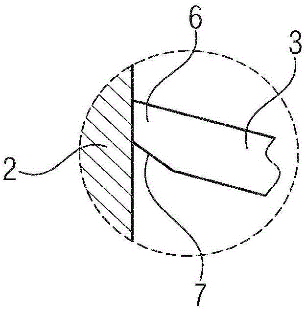
[0019] Figure 2a The valve flap 3 is shown in a position closed to the flow channel 2 in which the valve flap 3 is inclined at an angle of 84° relative to the flow channel 2 . The valve flap 3 has a peripheral edge 6 which has a smaller thickness than the valve flap 3 . The transition from the valve flap 3 to its surrounding edge 6 is designed in the form of a continuous and straight bevel 7 . In this position of the valve flap 3, the be...


PUM


Abstract

A valve device for a motor vehicle, having a housing (1), a flow channel (2) located in the housing, a flap (3) arranged in the flow channel (2) for closing the flow channel (2), wherein the flap (3) has regions in which a shaft (4) penetrating the flap (3) is fastened, and the shaft (4) is mounted rotatably in the housing (1), and a valve seat (5) which is arranged in the flow channel (2) and is in contact with the flap (3) in the closed position thereof. The peripheral edge (6) of the flap (3) has a thickness which is smaller than the thickness of the flap (3).

Description

technical field [0001] The invention relates to a valve arrangement for a motor vehicle with a housing, a flow channel in the housing, a valve plate arranged in the flow channel for closing the flow channel, and a valve seat arranged in the flow channel, In this case, the valve flap is fastened on a shaft, which is rotatably supported in the housing, and the valve seat is in contact with the valve flap in the closed position of the valve flap. Background technique [0002] Such valve arrangements are used, for example, as in-line throttle valves or exhaust gas recirculation valves and have been known for a long time. By means of the rotatably mounted valve flap, the flow channel can be completely closed or opened in order to regulate the mass flow. Icing occurs here when the environment has a negative influence on the flow channel and the valve plate. The result of the icing is to interfere with the smooth / uniform movement of the disc. In the worst case, icing can block / s...

Claims


Application Information

Patent Timeline
IPC IPC(8): F16K1/22
CPCF16K1/222F02D9/1015F02M25/0793F02M26/70
Inventor P·维尔特罗斯S·科勒
Owner CONTINENTAL AUTOMOTIVE GMBH
Learn More