A Transient Electromagnetic Method Pulse Current Transmitting Circuit

A transient electromagnetic method and pulse current technology, applied in the direction of pulse duration/width modulation, etc., can solve the problems of affecting receiver data acquisition, large voltage switching loss, large current reverse overshoot, etc., to shorten time and eliminate Resonance, reduce the effect of overshoot and shock

Inactive Publication Date: 2017-09-26
JILIN UNIV
View PDF3 Cites 0 Cited by
  • Summary
  • Abstract
  • Description
  • Claims
  • Application Information

AI Technical Summary

Problems solved by technology

[0004] The technical problem to be solved by the present invention is to provide a transient electromagnetic method pulse current transmitting circuit, which solves the problem that the switching tube of the upper bridge arm of the H-bridge circuit performs PWM hard-opening technology to control the voltage switching loss at both ends; after the H-bridge circuit is turned off The reverse overshoot of the falling edge current is large, and the oscillation tail time is long, which affects the data acquisition of the receiver

Method used


Image

  • A Transient Electromagnetic Method Pulse Current Transmitting Circuit
  • A Transient Electromagnetic Method Pulse Current Transmitting Circuit
  • A Transient Electromagnetic Method Pulse Current Transmitting Circuit

Examples


Embodiment Construction

[0019] In order to make the object, technical solution and advantages of the present invention more clear, the present invention will be further described in detail below in conjunction with the examples. It should be understood that the specific embodiments described here are only used to explain the present invention, not to limit the present invention.

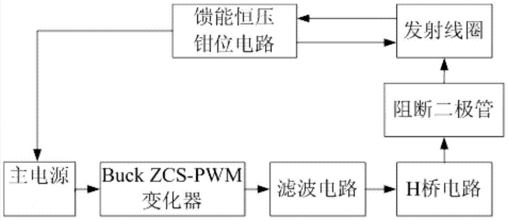
[0020] The emission current of magnetic source electromagnetic method includes two polarities of positive output and negative output, see figure 1 , block diagram of transient electromagnetic pulse current transmitting circuit, including: main power supply, Buck ZCS-PWM changer, H-bridge circuit, four blocking diodes, transmitting coil and energy-feeding constant voltage clamping circuit;

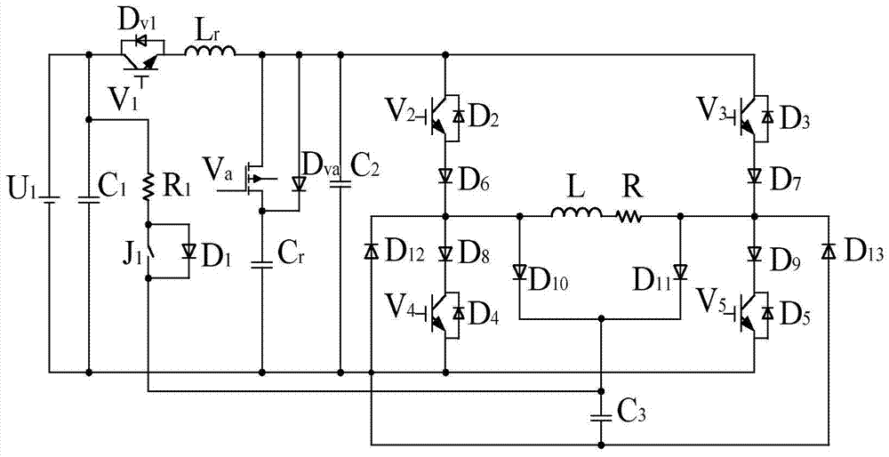
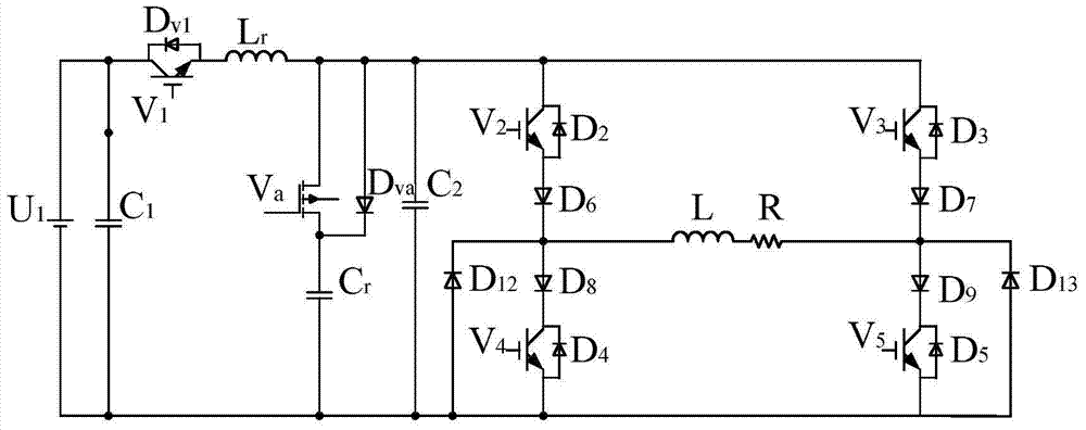
[0021] see figure 1 combine figure 2 , the main power supply U 1 It is connected with the Buck ZCS-PWM changer, and the voltage at both ends of the transmitting coil is controlled by the Buck ZCS-PWM changer to realize the control of...


PUM


Abstract

The invention relates to a pulse current transmission circuit adopting a transient electromagnetic method, and especially an emission current control circuit applicable to a multi-turn loop transmitting device of a magnetic source. A main power supply is connected with a Buck ZCS (Zero-Current-Switching)-PWM (Pulse-Width Modulation) converter, and the Buck ZCS-PWM converter controls the voltage at the two ends of a transmitting coil, so that the current of a rising edge and a flat top segment can be controlled; the Buck ZCS-PWM converter is connected with an H-bridge circuit, so as to control the current flow and realize that an emission current waveform is a bipolar trapezoidal wave; the H-bridge circuit is connected with the transmitting coil, and block diodes are connected to joints of the upper and lower bridge arms of the H-bridge circuit and the transmitting coil; the block diode is used for blocking the current of the transmitting coil from flowing towards the upper and lower bridge arms of the H-bridge circuit, and the blocking eliminates resonance caused by the current between a parasitic capacitor of the circuit and the transmitting circuit; the two ends of the transmitting coil are connected to an energy feedback constant voltage clamping circuit in parallel, wherein the energy feedback constant voltage clamping circuit controls a current falling edge, so that a clamp voltage of the current falling edge is improved and the falling edge time is shortened.

Description

technical field [0001] The invention relates to a transient electromagnetic pulse current transmitting circuit, in particular to a transmitting current control circuit suitable for a multi-turn coil transmitting device of a magnetic source. Background technique [0002] Magnetic source electromagnetic method instruments usually use H-bridge circuit as the main power conversion circuit of the transmitting device, and the load is inductive. In order to reduce the power loss of the load resistance, a coil load with large inductance and small resistance is usually used, especially in the aviation electromagnetic method and downhole electromagnetic method. The size of the coil is limited in special occasions such as the law, and in fact most of them use small coils with multiple turns. Therefore, special requirements are put forward for the power conversion circuit of the magnetic source electromagnetic method transmitter. [0003] Since the resistance of the load coil is relati...

Claims


Application Information

Patent Timeline
Patent Type & Authority Patents(China)
IPC IPC(8): H03K7/08
Inventor 于生宝姜健陈旭孙长玉王鲲鹏朱占山韩哲鑫
Owner JILIN UNIV
Why Eureka
Try Eureka