Antenna structure with metal backshell
A metal back shell and antenna structure technology, which is applied to antenna equipment with additional functions, antenna supports/mounting devices, etc., can solve problems such as inability to receive antenna signals, achieve simple processing technology, reduce occupied positions, and improve The effect of space utilization
- Summary
- Abstract
- Description
- Claims
- Application Information
AI Technical Summary
Problems solved by technology
Method used
Image
Examples
Embodiment 1
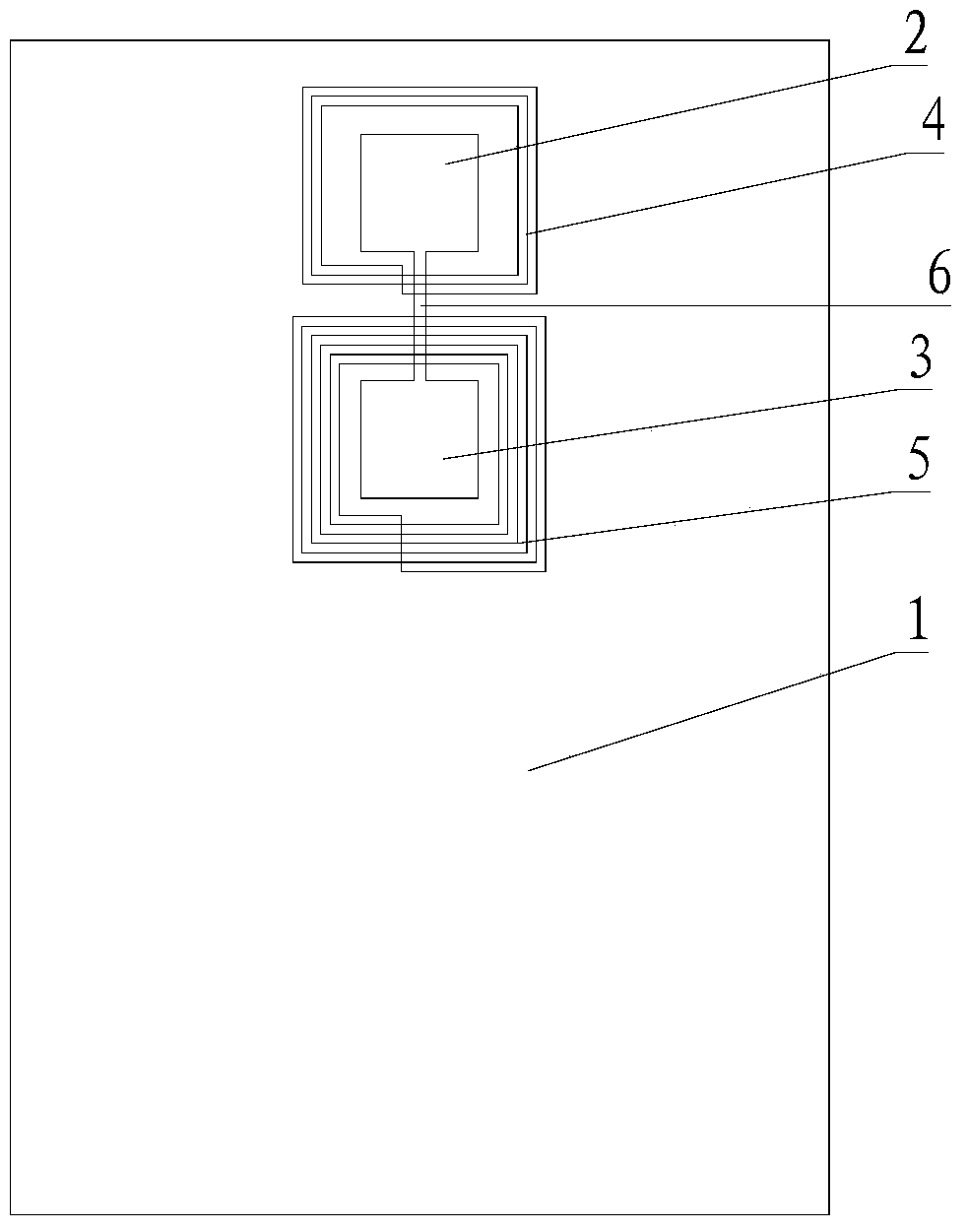
[0031] Please refer to figure 2 , Embodiment 1 of the present invention is:
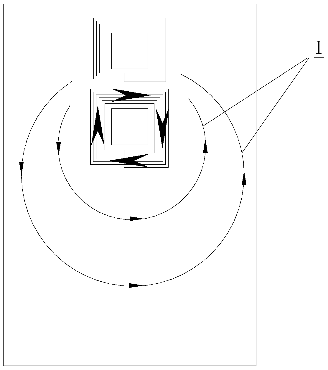
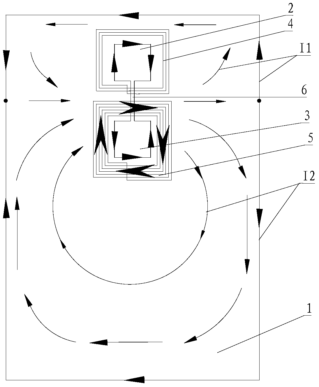
[0032] An antenna structure with a metal back shell, comprising a metal back shell 1, an NFC antenna coil 4 and a WPC antenna coil 5, the metal back shell 1 is an all-metal back shell, and the metal back shell includes a first through hole 2 and The second through hole 3, the first through hole 2 shown in the figure is located below the second through hole 3, in fact the two can also exchange positions, and even the two can be in a left-right positional relationship; the first through hole 2 and the second through hole 3 can be used to install a fingerprint recognition module, a camera module, a flash module or other sensor modules, respectively; One side, and the NFC antenna coil 4 is arranged around the first through hole 2, the WPC antenna coil 5 is arranged around the second through hole 3, and the metal back shell 1 is also provided with a first gap 6, the The first slot 6 connects the first ...
Embodiment 2
[0042] Please refer to Figure 7 , Embodiment 2 of the present invention further increases through holes on the basis of Embodiment 1, such as 3, 4, 5 through holes, and multiple through holes can be connected through multiple gaps; NFC antenna coil and WPC The antenna coil can be arranged around any two through holes, but usually a larger through hole is selected to obtain better performance. Figure 7 Shown is the case of three through holes, the three through holes can be a combination of fingerprint recognition through holes, camera through holes and flash light through holes, and a second gap 8 can be provided between the first through hole 2 and the third through hole 7 . It should be pointed out here that the first slit 6 in the up-down direction must be opened, while the second slit 8 in the left-right direction may not be opened. However, compared with the situation without the second slot 8, the performance of the NFC antenna and the WPC antenna will be enhanced wi...
Embodiment 3
[0044] Please refer to Figure 8 The difference between the third embodiment of the present invention and the first embodiment is that the coils of the NFC antenna and the WPC antenna are surrounded on the same through hole, Figure 8 2 shows that both coils surround the second through hole, wherein the inner circle is placed with the NFC antenna coil, and the outer circle is placed with the WPC antenna coil; it is also possible to place the inner circle with the WPC antenna coil and the outer circle with the NFC antenna coil. In this case, the difference from the first embodiment is that except that the NFC antenna coil and the WPC antenna coil are arranged on the same through hole, the others are the same as the embodiment, and the eddy current generated on the metal back shell can be changed as well. distribution, which enhances the performance of the antenna, so that in this case, the signal of the antenna can also be detected outside the metal rear case.
[0045] In summ...
PUM
 Abstract
Description
Claims
Application Information
 - R&D
- Intellectual Property
- Life Sciences
- Materials
- Tech Scout
- Unparalleled Data Quality
- Higher Quality Content
- 60% Fewer Hallucinations
Browse by: Latest US Patents, China's latest patents, Technical Efficacy Thesaurus, Application Domain, Technology Topic, Popular Technical Reports.
© 2025 PatSnap. All rights reserved.Legal|Privacy policy|Modern Slavery Act Transparency Statement|Sitemap|About US| Contact US: help@patsnap.com


