Spindle deformation analysis device
A deformation analysis and spindle technology, applied in electromagnetic measuring devices, electric/magnetic solid deformation measurement, machine gear/transmission mechanism testing, etc., to achieve good measurement accuracy
- Summary
- Abstract
- Description
- Claims
- Application Information
AI Technical Summary
Problems solved by technology
Method used
Image
Examples
Embodiment 1
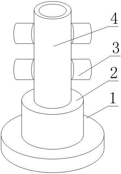
[0018] Such as figure 1 As shown, a spindle deformation analysis device includes a shaft sleeve 4 and a sensor 3 arranged on the shaft sleeve 4, the sensor 3 is more than one, and the sensors 3 are all fixed on the side wall of the shaft sleeve 4, and the sensor 3 are electric induction sensors 3, the measurement points of each sensor 3 are not located on the same straight line, and the side wall of the shaft sleeve 4 is also provided with an electric heating coil.
[0019] In this embodiment, the provided shaft sleeve 4 is used to fix each sensor 3. When the shaft sleeve 4 is sleeved on the main shaft, each sensor 3 forms a plurality of non-contact sensors 3 relative to the main shaft to be measured, so that , this structure can be more conveniently installed on the main shaft of the lathe to complete the dynamic error and thermal deformation analysis of the main shaft; furthermore, the sensor 3 is further limited by the electric induction sensor 3, which can make the sensor ...
Embodiment 2
[0021] The present embodiment is further limited on the basis of embodiment 1, as figure 1 As shown, the further technical solution is: in order to facilitate the replacement of sensor 3 types or models according to specific measurement needs, the sensors 3 are provided with magnetic bases 1, and each sensor 3 is magnetically adhered to the sensor 3 by the magnetic base 1 on each On the shaft sleeve 4.
[0022] In order to make this structure have the function of braking the rotation of the main shaft, so as to enrich the scope of application of this structure, for example, it can be used for the test and analysis of a single main shaft that has been disengaged, and also includes a driving part 2 fixed at any end of the shaft sleeve 4 .
[0023] In order to facilitate the fixing of this structure, the base 1 is also fixed on the free end of the driving part 2 .
Embodiment 3
[0025] This embodiment is further limited on the basis of any one of the solutions provided by the above embodiments. In order to enable this structure to conveniently complete the measurement of the inclination and deflection of the main shaft, and the error analysis on the X-axis, Y-axis and Z-axis, the The number of sensors 3 is at least five.
PUM
 Abstract
Description
Claims
Application Information
 - R&D
- Intellectual Property
- Life Sciences
- Materials
- Tech Scout
- Unparalleled Data Quality
- Higher Quality Content
- 60% Fewer Hallucinations
Browse by: Latest US Patents, China's latest patents, Technical Efficacy Thesaurus, Application Domain, Technology Topic, Popular Technical Reports.
© 2025 PatSnap. All rights reserved.Legal|Privacy policy|Modern Slavery Act Transparency Statement|Sitemap|About US| Contact US: help@patsnap.com

