Flat plate inclination measurement device based on multi-point off-focus detection

A technology of tilt measurement and flat panel, which is applied in the direction of measuring device, measuring tilt, surveying and navigation, etc., can solve the problems of limited detection range, limitation, adjustment lag, etc., and achieve the improvement of practicality, fast and timely adjustment process, and simplified structure. Effect

Active Publication Date: 2015-12-02
HEFEI UNIV OF TECH
View PDF9 Cites 3 Cited by
  • Summary
  • Abstract
  • Description
  • Claims
  • Application Information

AI Technical Summary

Problems solved by technology

[0003] At present, the commonly used detection method for the tilt degree of the flat plate is to use reflected light detection. One is to use an area array detection device, such as a CCD camera, to detect the position of the reflected light point on the image plane and then determine the tilt direction. This method requires image Processing and conversion of the digital signal can be provided to the adjustment mechanism to adjust the inclination. The problem is that the signal processing has a time process, which will cause adjustment lag, and the measurement process may not be carried out smoothly due to the clarity of the imaging; The other is to use a linear array detector, such as a linear array CCD, to detect the position of the reflected light spot. Although this method is fast, it can only detect a single direction of inclination. Two sets of detection devices are required for detection in different directions of X and Y. It can be realized; there is also the position change of the reflected light spot on the multi-quadrant detector to determine the tilt, but this method is limited by the sensitive area of ​​the detector, and thus limits the detection range

Method used


Image

  • Flat plate inclination measurement device based on multi-point off-focus detection
  • Flat plate inclination measurement device based on multi-point off-focus detection
  • Flat plate inclination measurement device based on multi-point off-focus detection

Examples


Embodiment Construction

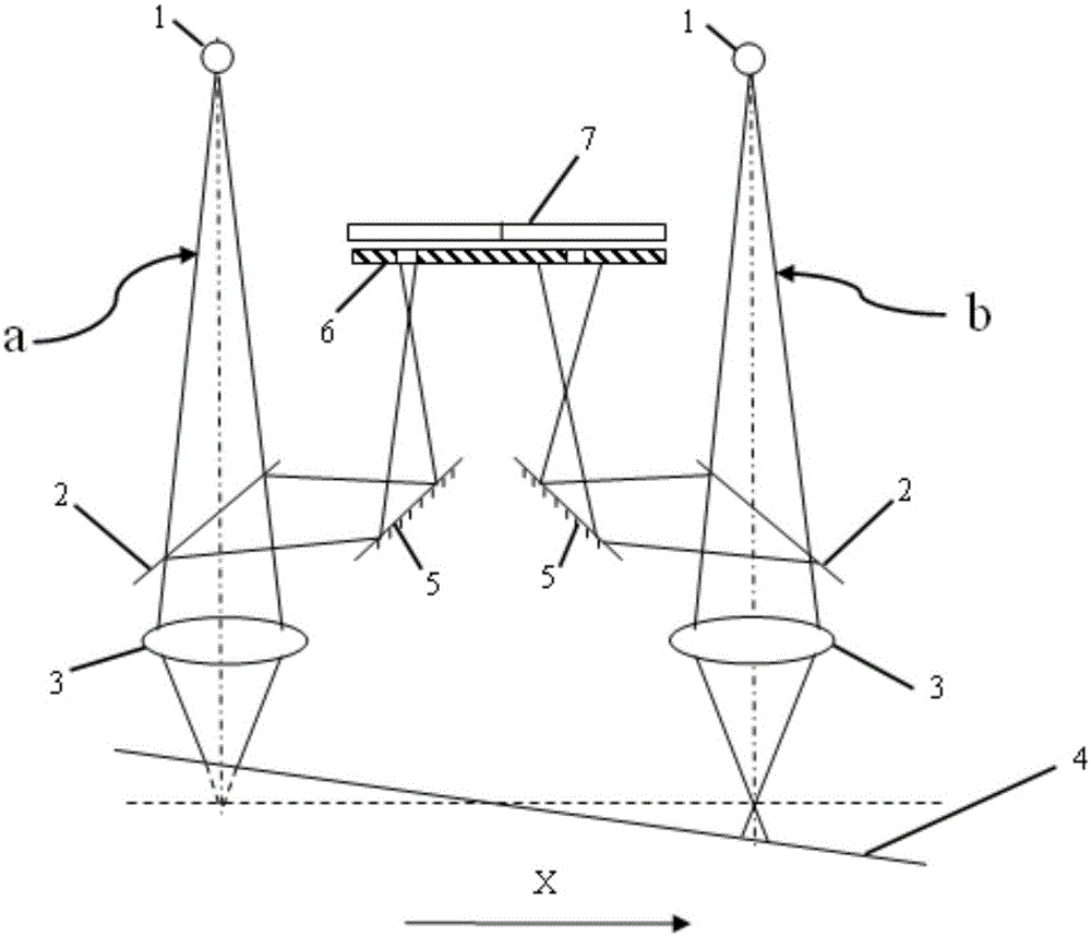
[0026] see figure 1 In the present embodiment, the detection optical path is set as follows: a point light source 1 is used as an illumination light source, and the point light source 1 is irradiated on the point to be measured of the flat plate 4 through the half mirror 2 and the objective lens 3, and the The surface of the point to be measured on the measuring plate 4 forms reflected light; the reflected light is reflected to the half-mirror 2 through the objective lens 3, and in the half-mirror 2, beams are split at 5:5 to form an optical axis A first light beam and a second light beam that are 90° to each other; the second light beam passes through the mirror 5 and passes through the pinhole in the pinhole plate 6 to project on the central position of a certain quadrant of the four-quadrant detector 7;

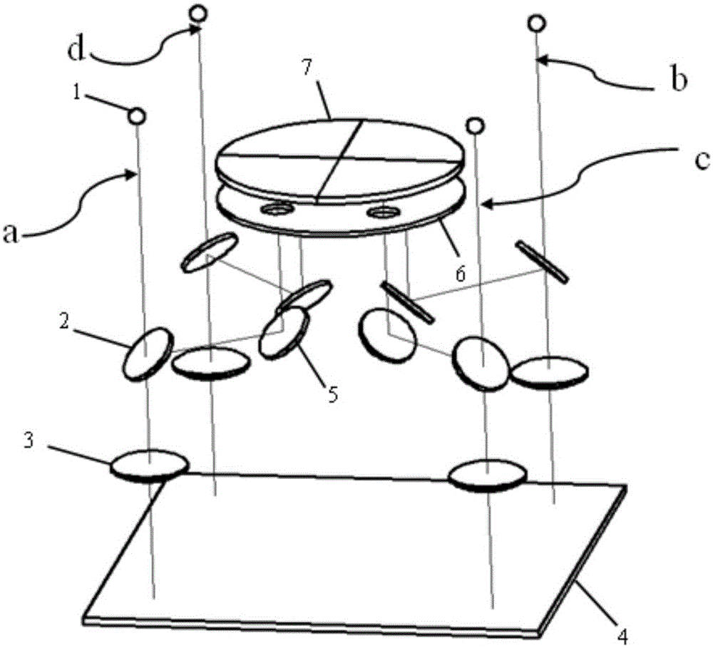
[0027] see figure 2 , image 3 and Figure 4 In this embodiment, the flat plate tilt measurement device based on multi-point defocus detection is provided with four de...


PUM


Abstract

The invention discloses a flat plate inclination measurement device based on multi-point off-focus detection. The flat plate inclination measurement device is characterized in that detection light paths take a point light source as an illumination light source and light is illuminated on a point to be detected of a detected flat plate through a semitransparent and semi-reflection mirror and an objective lens; the reflected light is projected to a certain quadrant of a four-quadrant detector through the objective lens, the semitransparent and semi-reflection mirror and a reflection mirror via pinholes in a pinhole plate; the four detection light paths are arranged, have the same structure form, and are rotationally symmetrical on the center of the four-quadrant detector; the four pinholes on the pinhole plate correspond to the center of the four-quadrant detector in position one by one; and light intensity difference information detected by four quadrants of the four-quadrant detector is compared to judge inclined states of the detected flat plate in X and Y directions. The flat plate inclination measurement device can carry out four-point synchronous detection on an inclination degree of the detected flat plate, realize rapid measurement of the inclined state of the flat plate and provide a detection signal; and a detection range is not limited by the area of the detector and the structure is simplified.

Description

technical field [0001] The invention relates to a flat panel inclination measuring device, in particular to a flat panel inclination measuring device based on multi-point defocus detection. Background technique [0002] In the defect detection of large TFT-LCD glass substrates and color filters, microscopic imaging is needed to realize the imaging detection of liquid crystal substrates. During the detection process, the microscope adopts high-resolution imaging, and the depth of field is small. The vibration of the substrate under test and the change of the positioning height make the small displacement of the plate in the height direction cause out-of-focus phenomenon. Although the automatic focus lens system is adopted to realize the focused imaging of the measured flat surface, it is all focused on a certain point of the flat. If the measured plate is tilted, it will cause the microscopic imaging surface to be partially focused and partially out of focus, which will seri...

Claims


Application Information

Patent Timeline
Patent Type & Authority Applications(China)
IPC IPC(8): G01C9/00G01C9/02
CPCG01C9/00G01C9/02
Inventor 王永红柏天舒但西佐闫佩正涂思琪卢荣胜
Owner HEFEI UNIV OF TECH
Why Eureka
Try Eureka