
Control Method of Gravity Compensated Vertical Subsystem Based on Sliding Mode Surface

A technology of gravity compensation and control method, which is applied to the simulation device of space navigation conditions, space navigation equipment, transportation and packaging, etc., and can solve the problem of large area occupied by air compression processing equipment, no modeling control algorithm, and marble cost Expensive and other issues, to achieve the effect of fast speed, reduced complexity, and reduced area

Active Publication Date: 2017-07-07
BEIHANG UNIV
View PDF8 Cites 0 Cited by
  • Summary
  • Abstract
  • Description
  • Claims
  • Application Information

AI Technical Summary

Problems solved by technology

The patent application number is CN201220400797 "Semi-active gravity compensation structure air bearing six degrees of freedom analog satellite device" announced a "parallel connection" scheme through the integration of motor ball screw and cylinder suspension to compensate the gravity of the spacecraft and It provides the freedom of movement in the vertical direction, which solves the problem that the air flotation method can only simulate the movement of five degrees of freedom, but its structure is relatively complicated, the air compression processing equipment occupies a large area, and the cost of marble is expensive; the patent application number is CN201410142865 "A Vertical Constant Force System" published a vertical constant force system composed of a balance point constant force spring module, a rack and pinion compensation module and a data acquisition control module, but did not give a specific modeling control algorithm

Method used

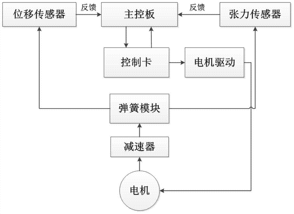

Image

  • Control Method of Gravity Compensated Vertical Subsystem Based on Sliding Mode Surface
  • Control Method of Gravity Compensated Vertical Subsystem Based on Sliding Mode Surface
  • Control Method of Gravity Compensated Vertical Subsystem Based on Sliding Mode Surface

Examples


Embodiment Construction

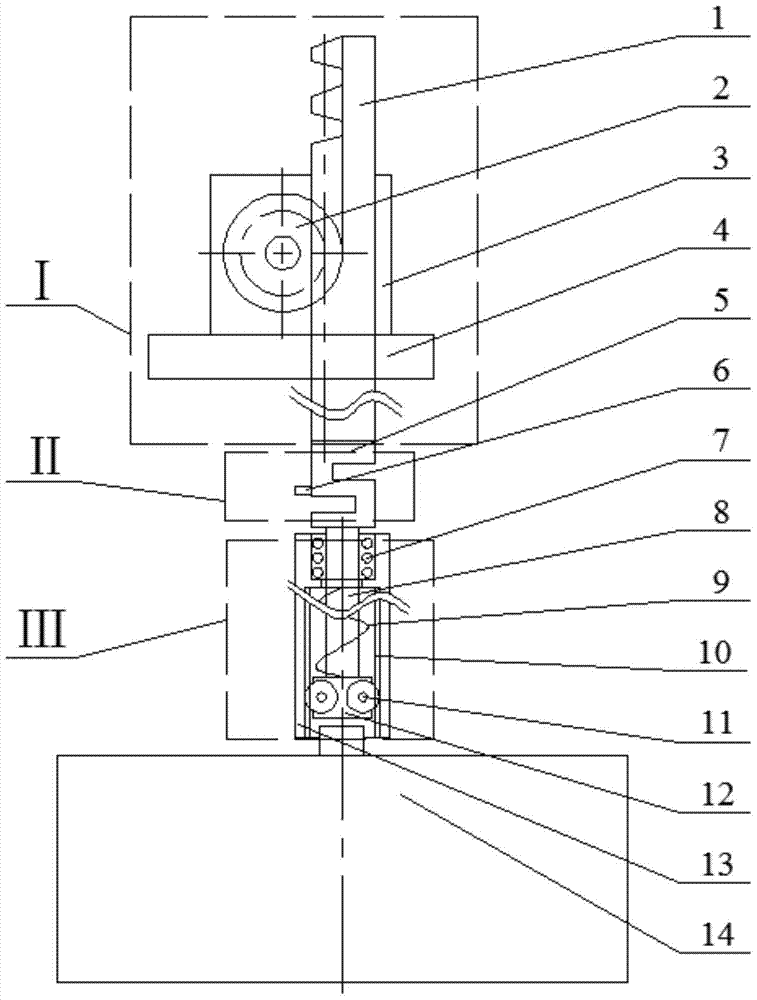
[0037] combine figure 1 , the actuator I includes a rack 1, a gear 2, a servo motor 3 and a motor mounting plate 4, the gear 2 is mounted on the motor shaft of the servo motor 3 fixed to the motor mounting plate 4, the rack 1 and the gear 2 are meshed and Driven by it to move; the sensing unit II includes a tension sensor 5 and a displacement sensor 6, the tension sensor 5 measures the force on the compression spring 9, the tension sensor 5 is installed on the lower end of the rack 1, and the displacement sensor 6 is installed on the side of the tension sensor 5 , the displacement sensor 6 measures the length variation of the compression spring 9; the spring module III includes a linear bearing 7, a guide rod 8, a compression spring 9, a rolling bearing 11, a bearing bracket 12 and a spring connecting sleeve 13, and the guide rod 8 is connected to the tension sensor 5 The lower end is matched with the linear bearing 7, and the lower end is equipped with a bearing bracket 12 fo...


PUM


Abstract

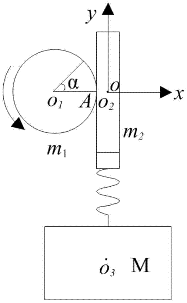
The invention discloses a gravity compensation vertical subsystem control method based on a slip form face. A gravity compensation vertical subsystem composed of a controller, a sensing unit, an executer and a spring module is provided. A coordinate system is established based on a working principle of the gravity compensation vertical subsystem. The system is modeled through a lagrange equation, a model is simplified, and a simplified spring mass system with the interference, model indeterminancy and outside motivation is obtained. According to the characteristics of the system model, a PID algorithm, a PISS algorithm and a PISST algorithm suitable for different task requirements are given according to the different task requirements. The three algorithms are integrated, algorithm selection is finished by setting parameters of the controller, and a criterion for parameter adjustment of the three algorithms is given. The gravity compensation vertical subsystem control method has the beneficial effects that a tension sensor and a displacement sensor are comprehensively applied, the compensation precision is improved, the comprehensive degree of the controller is high, and parameters are easy to adjust.

Description

[0001] Technical field [0002] The invention belongs to the technical field of ground verification of spacecraft navigation, guidance and control systems, and in particular relates to modeling and control of a vertical constant force system. Background technique [0003] Aerospace engineering is a high-risk, high-investment, high-reward, highly complex and high-precision system engineering. Its development level determines whether it can seize the high-tech commanding heights and maximize the use of space resources. There is no doubt that it is imminent to actively carry out aerospace technology research in our country. However, the space environment is extremely harsh. In order to successfully complete space missions, sufficient experiments must be carried out on the ground. Therefore, various space agencies at home and abroad attach great importance to the experimental verification of spacecraft on the ground. [0004] One of the most important features of the space environ...

Claims


Application Information

Patent Timeline
Patent Type & Authority Patents(China)
IPC IPC(8): B64G7/00
Inventor 贾英民贾娇孙施浩
Owner BEIHANG UNIV
Learn More