Straight Cutting Stapler with Intermediate Bridge Structure
A bridge-type, straight-line technology, applied in the field of medical devices, can solve the problems of cumbersome and increased operation time, and achieve the effect of simplifying the operation
- Summary
- Abstract
- Description
- Claims
- Application Information
AI Technical Summary
Problems solved by technology
Method used
Image
Examples
Embodiment 1
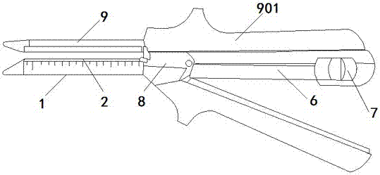
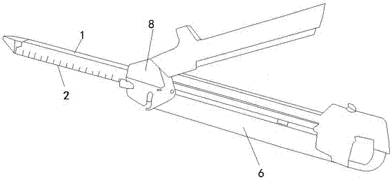
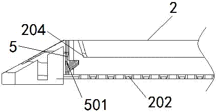
[0033] Embodiment 1: as Figure 1~5 and Figure 8 As shown, the linear cutter and stapler with a bridge structure includes a staple cartridge seat 1, a staple cartridge 2, a cutting knife 3, a sliding knife rail 4, and an anvil 9; the staple cartridge 2 is installed on the staple cartridge seat 1, The nail anvil 9 is detachably connected to the magazine base 1; the magazine base 1 is provided with a sliding knife rail 4 along the central axis direction, and the staple magazine 2 is provided with a sliding knife groove 201 along the central axis direction at the corresponding position of the sliding knife rail 4 , and the sliding knife groove 201 and the staple bin 2 form two spaces; the cutting knife 3 is installed in the sliding knife rail 4, the front end of the cutting knife 3 has a cutting part 301, the cutting knife 3 slides along the sliding knife rail 4, and the sliding knife rail 4 The bottom of the front end is provided with a spacer 401, and the bottom of the front ...
Embodiment 2
[0035] Embodiment 2: as Figure 6~7 As shown, the difference between the linear cutting stapler with bridge structure and Embodiment 1 is that the rear end of the nail anvil 2 has a groove 902, specifically, the linear cutter stapler with bridge structure includes staples Cartridge 1, staple cartridge 2, cutting knife 3 and sliding knife rail 4, staple cartridge 2 is installed on staple cartridge seat 1, staple cartridge seat 1 is provided with sliding knife rail 4 along the central axis direction, staple cartridge 2 is on the sliding knife rail The corresponding position of 4 is provided with a sliding knife groove 201 along the central axis direction, and the sliding knife groove 201 and the staple bin 2 form two spaces; the cutting knife 3 is installed in the sliding knife rail 4, and the front end of the cutting knife 3 has a cutting part 301 for cutting Knife 3 is movably connected with sliding knife rail 4, and cutting knife 3 can slide in sliding knife rail 4, and the r...
Embodiment 3
[0037] Embodiment 3: as Figure 8~9 As shown, the linear cutting stapler of the bridge structure includes a staple cartridge seat 1, a staple cartridge 2, a cutting knife 3 and a sliding knife rail 4, and the staple cartridge 2 is installed on the On the staple cartridge holder 1, the staple cartridge holder 1 is provided with a sliding knife rail 4 along the central axis direction, and the staple cartridge 2 is provided with a sliding knife groove 201 along the central axis direction at the corresponding position of the sliding knife rail 4, and the sliding knife groove 201 and the nail The warehouse 2 forms two spaces; a cutting knife 3 is installed in the sliding knife rail 4, and the front end of the cutting knife 3 has a cutting part 301. The cutting knife 3 and the sliding knife rail 4 are movably connected, and the cutting knife 3 can slide in the sliding knife rail 4 The surface of the rear end of the sliding knife groove 201 is also provided with a partition 205, and ...
PUM
 Abstract
Description
Claims
Application Information
 - Generate Ideas
- Intellectual Property
- Life Sciences
- Materials
- Tech Scout
- Unparalleled Data Quality
- Higher Quality Content
- 60% Fewer Hallucinations
Browse by: Latest US Patents, China's latest patents, Technical Efficacy Thesaurus, Application Domain, Technology Topic, Popular Technical Reports.
© 2025 PatSnap. All rights reserved.Legal|Privacy policy|Modern Slavery Act Transparency Statement|Sitemap|About US| Contact US: help@patsnap.com


