
High-temperature testing clamp of piezoelectric polarization device

A test fixture and piezoelectric technology, applied in the direction of measuring devices, instruments, scientific instruments, etc., can solve the problems of small-sized samples that cannot be polarized, waste of polarized silicone oil, and inconvenient operation, and achieve good fixing effect and easy operation , the effect of simple structure

Active Publication Date: 2015-11-25
CHINA JILIANG UNIV
View PDF7 Cites 9 Cited by
  • Summary
  • Abstract
  • Description
  • Claims
  • Application Information

AI Technical Summary

Problems solved by technology

The test fixture structure design of the traditional piezoelectric polarization device is generally unreasonable and inconvenient to operate, especially for small-sized samples that cannot be polarized. In addition, the sample pool is too large, resulting in a serious waste of polarized silicone oil.

Method used


Image

  • High-temperature testing clamp of piezoelectric polarization device
  • High-temperature testing clamp of piezoelectric polarization device
  • High-temperature testing clamp of piezoelectric polarization device

Examples


Embodiment Construction

[0018] The present invention will be further described in detail below in conjunction with the accompanying drawings and specific embodiments.

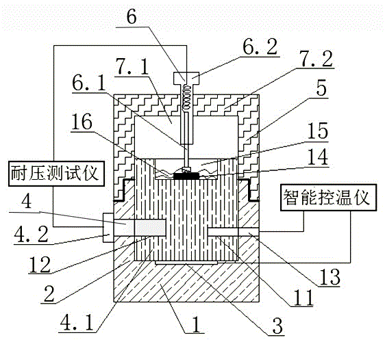
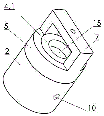
[0019] Such as Figure 1-3 As shown, the high temperature test fixture of the piezoelectric polarization device of the present invention includes a support base 1, a lower sheath 2, a heating element 3, a lower electrode 4, an upper sheath 5 and an upper electrode 6, and the support base 1 and the lower The sheath 2 forms an organic whole, the support base 1 is provided with a card slot, the heating element 3 is a circular ceramic heating chip, and the circular ceramic heating chip is installed in the card slot, and the lower electrode 4 It includes a copper column 4.1 with a circular groove on the upper end and a threaded rod terminal 4.2. The copper column 4.1 is installed on the support base 1 and is closely attached to the ceramic heating chip. The upper sheath 5 is provided with cutouts on both sides of the upper end 7.1, the up...


PUM

PropertyMeasurementUnit
depthaaaaaaaaaa

Abstract

The invention relates to a high-temperature testing clamp of a piezoelectric polarization device. The high-temperature testing clamp comprises a supporting base, a lower protecting bush, a heating element, a lower electrode, an upper protecting bush and an upper electrode, wherein the supporting base and the lower protecting bush form an organic whole body; a clamping groove is formed in the supporting base; the heating element is a circular ceramic heating sheet; the circular ceramic heating sheet is mounted in the clamping groove; the lower electrode comprises a copper column with a circular groove in the upper end and a thread rod wiring column; the copper column is mounted on the base and is fitted with the ceramic heating sheet; notches are formed in the two ends of the upper end of the upper protecting bush; the upper protecting bush is mounted above the lower protecting bush; the upper electrode comprises a spring probe and a thread pressing rod; the spring probe is inserted into the thread pressing rod; and the thread pressing rod is mounted on a transverse beam of the upper protecting bush. The testing clamp has a simple structure and low cost; the upper protecting bush and the lower protecting bush are connected in a concave-convex clamping manner and are tightly pressed up and down, so that the fixing effect is good, heat isolation and insulation are good and the utilization is safe; and the spring probe is used as a contact of the upper electrode and can be used for carrying out polarization testing on samples with different radial directions and thicknesses under a high temperature, and the operation is easy.

Description

technical field [0001] The invention belongs to the technical field of piezoelectric material performance testing, and in particular relates to a high-temperature test fixture of a piezoelectric polarization device. Background technique [0002] Piezoelectric material is a functional material that can convert mechanical energy and electrical energy. It is widely used in high-tech fields such as mobile communications, satellite broadcasting, electronic equipment, instrumentation, and aerospace, and has become an indispensable modern key material and component. With the rapid development of science and technology, piezoelectric materials need to have greater adaptability in terms of application range and use environment. Therefore, it is urgent to develop new piezoelectric materials with high Curie temperature, large piezoelectric coefficient, and high mechanical strength. Researching new piezoelectric components requires extensive experiments with different materials and proc...

Claims


Application Information

Patent Timeline
Patent Type & Authority Applications(China)
IPC IPC(8): G01N17/00
Inventor 张景基高亚峰王疆瑛王鸿
Owner CHINA JILIANG UNIV
Learn More