
Device for calibrating parallelism of optical axis of multi-axis optical system, and calibration method thereof

An optical system, optical axis parallel technology, applied in the direction of using optical devices, measuring devices, testing optical performance, etc., can solve the problems of high price, high site requirements, complex operation, etc., to reduce the difficulty of production and installation, and site requirements. Not high, easy to measure and operate

Inactive Publication Date: 2015-11-25
XIAN UNIV OF POSTS & TELECOMM
View PDF6 Cites 27 Cited by
  • Summary
  • Abstract
  • Description
  • Claims
  • Application Information

AI Technical Summary

Problems solved by technology

This method realizes angle detection by distance measurement, and the combination of multiple optical systems makes the caliber and volume of the equipment larger, which brings inconvenience to installation, commissioning and transportation.
For a multi-optical axis optical system without a rangefinder and a telescopic system, it is impossible to detect the parallelism of the optical axes. In addition, the system introduces many error factors, and the reliability of the measurement results is not high.
In recent years, scholars have proposed the use of ZYGO interferometers or collimator with reticles inside and capable of emitting a variety of spectra to calibrate the parallelism of the optical axes of the multi-axis optical system. These calibration methods exist in the manufacturing of testing equipment. Complicated or expensive, the system has high requirements on the site, bulky, functional modules need to be replaced during the calibration process, and the operation is complicated, etc.

Method used


Image

  • Device for calibrating parallelism of optical axis of multi-axis optical system, and calibration method thereof
  • Device for calibrating parallelism of optical axis of multi-axis optical system, and calibration method thereof
  • Device for calibrating parallelism of optical axis of multi-axis optical system, and calibration method thereof

Examples


Embodiment Construction

[0028] The following will clearly and completely describe the technical solutions in the embodiments of the present invention with reference to the accompanying drawings in the embodiments of the present invention. Obviously, the described embodiments are only some, not all, embodiments of the present invention. Based on the embodiments of the present invention, all other embodiments obtained by persons of ordinary skill in the art without making creative efforts belong to the protection scope of the present invention.

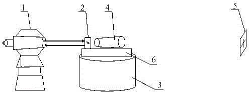
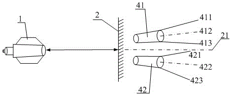
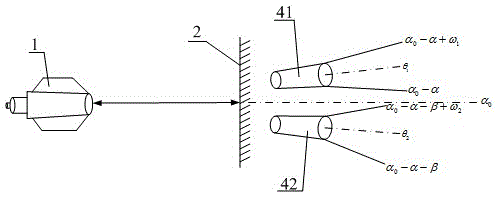
[0029] see figure 1 , in an embodiment of the present invention, a device for calibrating the parallelism of the optical axes of a multi-optical axis optical system includes a high-precision autocollimation theodolite, a plane mirror, a multi-optical axis optical system to be calibrated, a base, a cross target plate and a rotating The platform, the multi-optical axis optical system and the plane reflector are all installed on the base, and the plane reflector ...


PUM


Abstract

The invention discloses a device for calibrating parallelism of optical axes of a multi-axis optical system, and a calibration method thereof. The device comprises a high precision autocollimation theodolite, a planar mirror, a to-be-calibrated multi-axis optical system, a pedestal, a cross target plate and a rotary platform. The multi-axis optical system and the planar mirror are both disposed on the pedestal. The pedestal is placed on the rotary platform. The cross target plate is fixed in a position 1000 times of the longest lens focal length away from the front end of the optical system. The autocollimation theodolite is disposed behind the planar mirror and is used for aiming. Through rotation of the rotary platform many times, the direction values of the planar mirror, which are measured by aiming of the autocollimation theodolite, are obtained. The directions of optical axes can be known by calculating the direction values measured many times. The difficulties in manufacturing and installing detection equipment can be reduced, less requirements of places are needed, the measuring operation is convenient, high applicability is exhibited, and installation errors of the planar mirror are eliminated. The device is suitable for measuring or calibrating parallelism of optical axes of a multi-axis optical system and a multispectral multi-axis optical system.

Description

technical field [0001] The invention relates to the field of optical system measurement, in particular to a device for calibrating the parallelism of optical axes of a multi-optical axis optical system and a calibrating method thereof. Background technique [0002] The traditional method and device for correcting optical axis parallelism uses a large-diameter off-axis parabolic reflective collimator. The parallel light is reflected by the parabolic reflective collimator, the focus of the beam convergence is away from the optical axis, and the parallelism of the optical axis of the multi-axis optical system can be determined by the position of each focus. However, the system calibrated by this method has high requirements on the caliber and surface shape of the parabolic reflector, which makes the processing and manufacturing of the calibration equipment complicated, the cycle is long, and the cost is high. In addition, when the light source is replaced during the calibration...

Claims


Application Information

Patent Timeline
IPC IPC(8): G01B11/26G01B11/27G01M11/02
Inventor 李春艳巩稼民汤琦乔琳
Owner XIAN UNIV OF POSTS & TELECOMM
Learn More