Energy-saving hydrogen decrepitation device for production of rare earth magnetic materials

A magnetic material and rare earth technology, which is applied in the field of energy-saving hydrogen crushing devices for the production of rare earth magnetic materials, can solve the problems of low milling efficiency, waste of heat, and high energy costs of enterprises, so as to save warm-up time and reduce energy consumption. Cost, the effect of improving milling efficiency

Active Publication Date: 2015-11-25
SUZHOU SABO IND DESIGN
View PDF8 Cites 0 Cited by
  • Summary
  • Abstract
  • Description
  • Claims
  • Application Information

AI Technical Summary

Problems solved by technology

At present, the way of heating the hydrogen crushing furnace is that the hydrogen crushing furnace is in a rotating state, and the heating is carried out through the heating cover attached to the outside of the hydrogen crushing furnace. The heating cover is an open structure. After the first heating reaction is completed, the heating cover is retracted. , after the hydrogen crushing furnace is refilled, the heating mantle needs to be preheated again before heating, which not only wastes a lot of heat, but also causes high energy costs for the enterprise, and at the same time, the milling efficiency is low

Method used


Image

  • Energy-saving hydrogen decrepitation device for production of rare earth magnetic materials
  • Energy-saving hydrogen decrepitation device for production of rare earth magnetic materials
  • Energy-saving hydrogen decrepitation device for production of rare earth magnetic materials

Examples


Embodiment Construction

[0018] In order to make the technical means, creative features, goals and effects achieved by the present invention easy to understand, the present invention will be further described below in conjunction with specific illustrations.

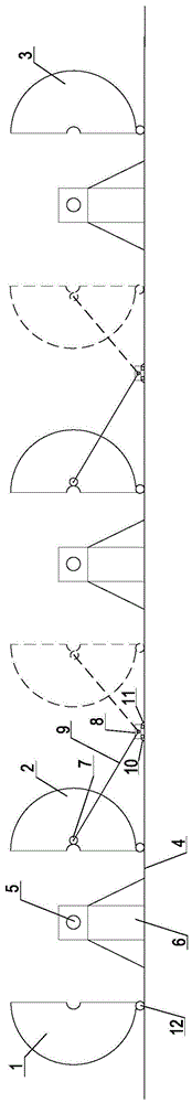
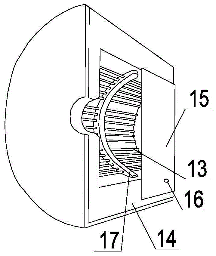
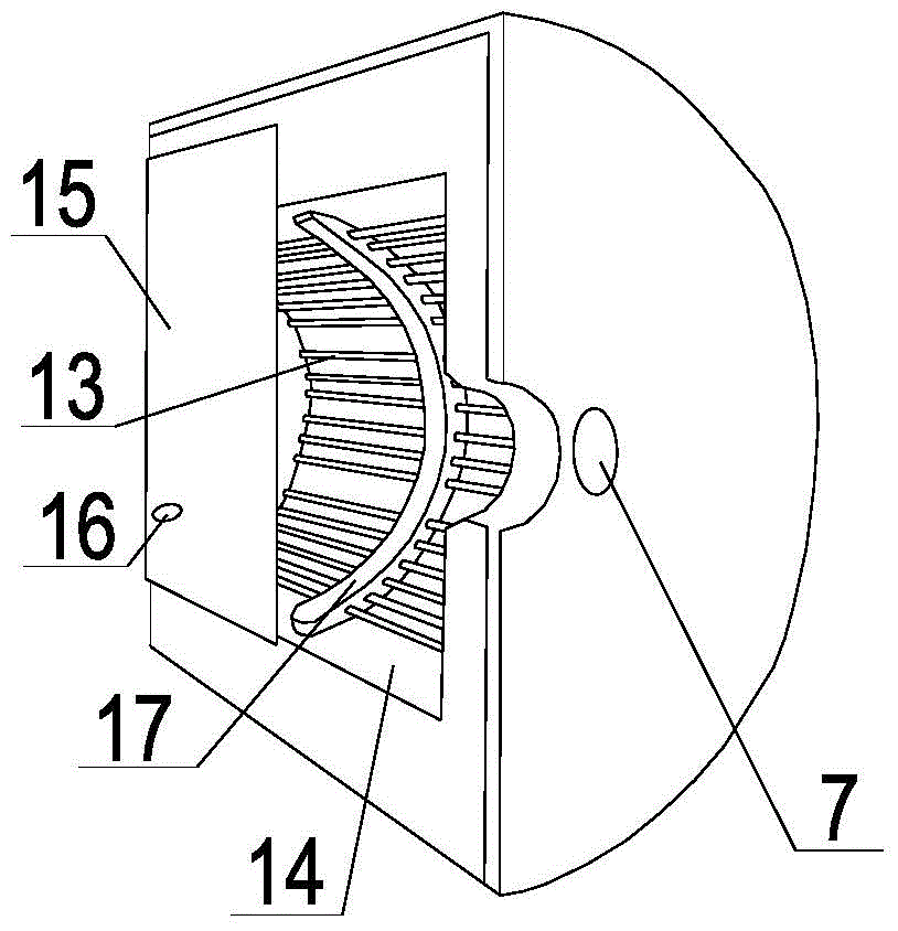
[0019] see Figure 1 ~ Figure 3 An energy-saving hydrogen crushing device for the production of rare earth magnetic materials, including a front heating chamber 1, a rotating heating chamber 2, a rear heating chamber 3, a guide rail 4, a reaction furnace 5, a reaction furnace installation frame 6, a fixed pin 7, a sliding frame 8, Connecting rod 9, slide front stop pin 10, slide back stop pin 11, pulley 12, heating pipe 13, heat insulation layer 14, baffle plate 15, travel switch 16 and limit frame 17.

[0020] In this embodiment, the front group hydrogen crushing mechanism, the middle group hydrogen crushing mechanism and the rear group hydrogen crushing mechanism are installed on the guide rail 4, wherein the front group hydrogen crushing mech...


PUM


Abstract

The invention provides an energy-saving hydrogen decrepitation device for production of rare earth magnetic materials. A front hydrogen decrepitation mechanism, a middle hydrogen decrepitation mechanism and a rear hydrogen decrepitation mechanism are mounted on a guide rail. The front hydrogen decrepitation mechanism comprises a front heating chamber, a reaction furnace and a rotary heating chamber. The middle hydrogen decrepitation mechanism comprises a pair of rotary heating chambers and a reaction furnace. The rear hydrogen decrepitation mechanism comprises a rotary heating chamber, a reaction furnace and a rear heating chamber. Each reaction furnace is mounted on a reaction furnace mounting frame. A steady pin is arranged on each rotary heating chamber. One end of a connecting rod is fixed to each rotary heating chamber through the corresponding steady pin. The other end of each connecting rod is mounted on a corresponding sliding support. The sliding supports are arranged on the guide rail. Each sliding support is provided with a front sliding stop pin and a rear sliding stop pin. The internal structure of the front heating chamber, the internal structures of the rotary heating chambers and the internal structure of the rear heating chamber are identical. The front heating chamber is internally provided with heating pipes. The heating pipes are arranged on a heat insulation layer. A baffle is mounted on the outer side of the heat insulation layer. A travel switch is arranged on the baffle. Through arrangement of the rotary heating chambers, the energy-saving hydrogen decrepitation device can conduct heating rapidly, and meanwhile the powder manufacturing efficiency is also improved.

Description

technical field [0001] The invention relates to the technical field of adding powder to rare earth magnetic materials, in particular to an energy-saving hydrogen crushing device for producing rare earth magnetic materials. Background technique [0002] Hydrogen crushing furnace is a kind of non-mechanical force to form ingot or flake rare earth alloy material into powder, mainly through hydrogen and rare earth alloy (such as neodymium iron boron alloy Nd 2 Fe 14 B) Reaction, using the intergranular fracture and transgranular fracture produced by the rare earth alloy (such as NdFeB alloy) in the process of hydrogen absorption and desorption, which leads to the pulverization of the rare earth alloy, forming an embrittlement and fragmentation process, thus obtaining A kind of process equipment for rare earth alloy powder with a certain particle size, and when the hydrogen crushing furnace prepares rare earth alloy powder, it needs to be heated by the outside. At present, the ...

Claims


Application Information

Patent Timeline
IPC IPC(8): B22F9/04
Inventor 丁会张苏陈力航
Owner SUZHOU SABO IND DESIGN
Why Eureka
Try Eureka