
Powder mass flow rate measuring device and method based on electrostatic and capacitive sensor arrays

A technology of electrostatic sensor and capacitive sensor, which is applied in mass flow measurement devices, indirect mass flow meters, etc., can solve the problems of particle concentration, uneven flow velocity distribution, large measurement error, unfavorable safe and efficient operation of industrial production process, etc.

Active Publication Date: 2015-11-18
SOUTHEAST UNIV
View PDF5 Cites 19 Cited by
  • Summary
  • Abstract
  • Description
  • Claims
  • Application Information

AI Technical Summary

Problems solved by technology

[0003] However, in the process of industrial gas-solid two-phase flow, because the solid phase particles are affected by many factors such as ambient temperature, humidity, and gas phase transportation speed, the distribution of particle concentration and flow velocity on the cross section of the pipeline is extremely uneven.
In flow measurement, if the concentration distribution and velocity distribution of solid particles in the cross-section of the pipeline are not considered, it will inevitably lead to large measurement errors, so that the accurate measurement and control of powder flow cannot be realized, which is not conducive to the safe and efficient operation of industrial production processes
Electrical capacitance tomography (ECT) technology can obtain the concentration distribution of solid phase particles in the pipeline section, but due to the complexity of its detection system and the large concentration measurement error caused by image reconstruction
Electrostatic sensors can realize particle velocity measurement, but for the case of cross-sectional velocity distribution, there is a large deviation in the average velocity measurement, so the flow rate also has a large measurement error

Method used


Image

  • Powder mass flow rate measuring device and method based on electrostatic and capacitive sensor arrays
  • Powder mass flow rate measuring device and method based on electrostatic and capacitive sensor arrays
  • Powder mass flow rate measuring device and method based on electrostatic and capacitive sensor arrays

Examples


Embodiment Construction

[0064] The present invention will be further explained below in conjunction with the accompanying drawings and specific embodiments. It should be understood that these embodiments are only used to illustrate the present invention and are not intended to limit the scope of the present invention. After reading the present invention, those skilled in the art all fall into the appended claims of the present application to the amendments of various equivalent forms of the present invention limited range.

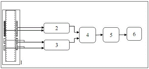
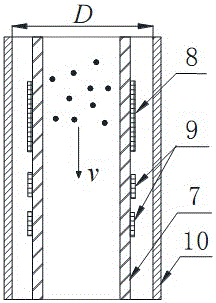
[0065] The working principle of the present invention is: according to the measured capacitance between the adjacent capacitor pole pieces of the capacitance sensor array, combined with the relationship between the output capacitance and the local concentration obtained through the experiment, the concentration distribution of the powder in the pipeline section is calculated. Using the electrostatic sensor array combined with the cross-correlation algorithm, the velocity distribu...


PUM


Abstract

The invention discloses a mass flow rate measuring device and method based on electrostatic and capacitive sensor arrays for powder particles in a pipeline. The powder mass flow rate measuring device comprises an electrostatic sensor array, a capacitive sensor array, a data collecting module and a data processing module; the data collecting module is used for collecting electrostatic signals between each pair of electrostatic electrode slices in the electrostatic sensor array and output signals between two adjacent capacitive electrode slices in the capacitive sensor array; the data processing module comprises a powder speed calculation unit, a powder concentration calculation unit and a powder mass calculation unit. According to the powder mass flow rate measuring device and method, concentration distribution and speed distribution of powder on the pipeline section are fully taken into account, and therefore accurate measurement on the powder mass flow rate is achieved.

Description

technical field [0001] The invention belongs to the technical field of flow measurement, in particular to a device and method for measuring the mass flow of powder particles in a pipeline based on an array of electrostatic and capacitance sensors. Background technique [0002] Gas-solid two-phase flow widely exists in industrial production processes such as petroleum, electric power, and chemical industry. Realizing the on-line and accurate measurement of gas-solid two-phase flow is of great significance to improving industrial production efficiency and realizing energy saving and environmental protection. At present, people have tried to develop a variety of flowmeters based on different detection principles, and used in industrial production, such as electrical method, optical method, acoustic method, radiation method and so on. [0003] However, in the process of industrial gas-solid two-phase flow, because the solid phase particles are affected by many factors such as a...

Claims


Application Information

Patent Timeline
Patent Type & Authority Applications(China)
IPC IPC(8): G01F1/86
Inventor 许传龙王胜南李健王式民
Owner SOUTHEAST UNIV
Learn More