
Ceiling structure with double underneath type parallel radiant tubes and construction method of ceiling structure

A construction method and radiant tube technology, applied in building components, heating methods, building structures, etc., can solve the problems of inconvenient maintenance of radiant tube 2', large distance from radiation to the room, loss of radiant tube 2', etc., and achieve enhanced Energy utilization efficiency, uniform distribution, and the effect of reducing heat loss

Inactive Publication Date: 2015-11-18
MOMA CHINA CO LTD +2
View PDF6 Cites 0 Cited by
  • Summary
  • Abstract
  • Description
  • Claims
  • Application Information

AI Technical Summary

Problems solved by technology

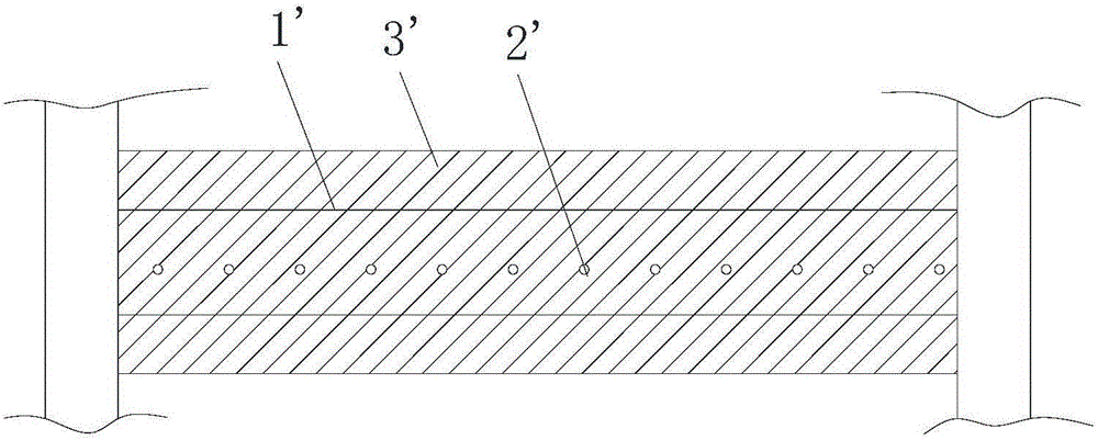
[0004] However, since the radiant tube 2' is arranged between the upper and lower layers of steel mesh, and the upper and lower sides of the steel bar layer 1' are covered with concrete, the heat of the radiant tube 2' radiates from the lower concrete to the indoor distance is relatively large. It will cause a large amount of heat loss in the radiant tube 2' in the concrete layer 3', and the heat transfer efficiency is not high
In addition, due to the need to leave enough space between the two layers of steel mesh to place the radiant tube 2', it will result in a large distance between the upper and lower layers of steel mesh, making the overall thickness of the ceiling structure larger, resulting in material loss more, increased cost
Since the radiant tube 2' is set between the upper and lower layers of steel mesh, and the steel mesh is poured together with the concrete layer 3', when the radiant tube 2' has a problem and needs to be replaced, the steel mesh must be removed before it can be repaired. The operation of replacing and maintaining the radiant tube 2' makes the maintenance of the radiant tube 2' very inconvenient and the maintenance cost is very high

Method used


Image

  • Ceiling structure with double underneath type parallel radiant tubes and construction method of ceiling structure
  • Ceiling structure with double underneath type parallel radiant tubes and construction method of ceiling structure
  • Ceiling structure with double underneath type parallel radiant tubes and construction method of ceiling structure

Examples


Embodiment Construction

[0013] Embodiments of the invention are described in detail below, but the invention can be practiced in many different ways as defined and covered by the claims.

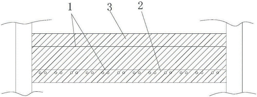
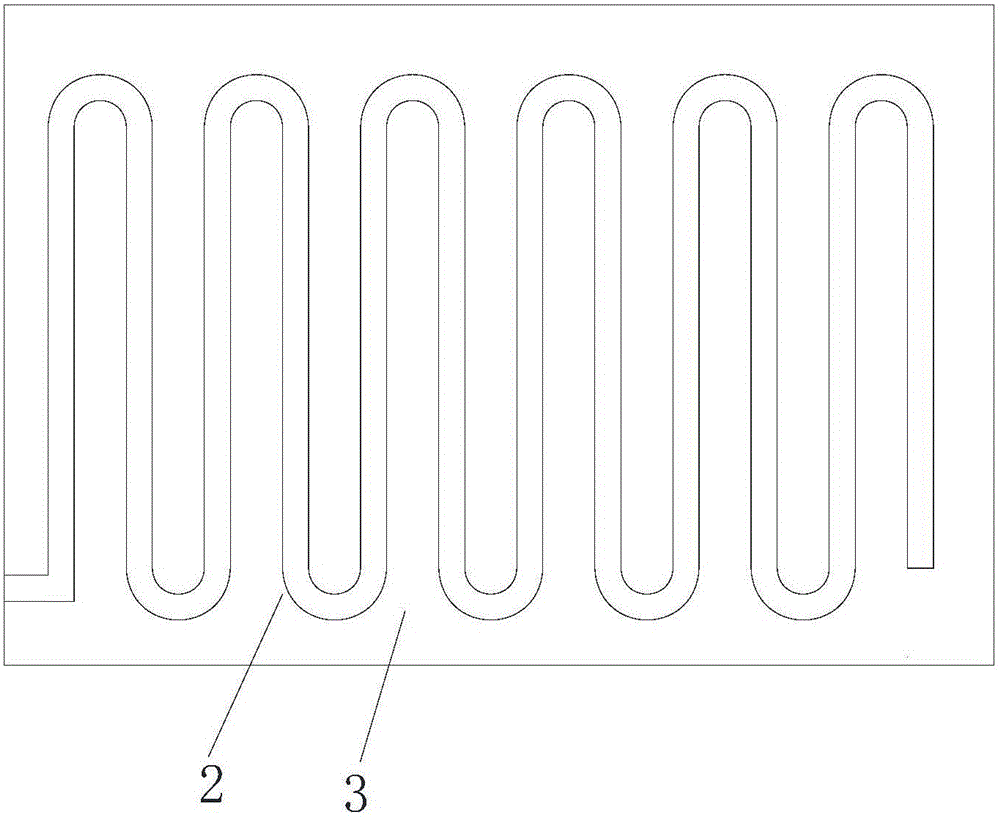
[0014] see figure 2 with image 3 As shown, according to the embodiment of the present invention, the double-parallel radiant tube under-mounted ceiling structure includes an integrally cast steel bar layer 1, radiant tube 2 and concrete layer 3, and the radiant tube 2 is located on the lower side of the steel bar layer 1, that is, close to the indoor On one side, the concrete layer 3 is covered outside the reinforcement layer 1 and the concrete layer 3, and the radiant tubes 2 are arranged in a double parallel structure.

[0015] In the double-parallel radiant tube under-mounted ceiling structure of the present invention, the radiant tube 2 is located on the lower side of the reinforcement layer 1, and is directly integrated with the concrete pouring in the process of forming the ceiling, which makes the middle ...


PUM


Abstract

The invention provides a ceiling structure with double underneath type parallel radiant tubes and a construction method of the ceiling structure. The ceiling structure with the double underneath type parallel radiant tubes comprises an integral pouring molded reinforcement layer (1), the radiant tubes (2) and a concrete layer (3); the radiant tubes (2) are positioned on the lower side of the reinforcement layer (1); the concrete layer (3) wraps the reinforcement layer (1); and the radiant tubes (2) are distributed to form a double parallel type structure. The ceiling structure with the double underneath type parallel radiant tubes is simple in structure, low in repairing difficulty, high in heat transfer efficiency and low in cost.

Description

technical field [0001] The invention relates to the technical field of building heating energy utilization, in particular to a ceiling structure with double parallel radiant tubes and a construction method thereof. Background technique [0002] With the rapid development of the domestic economy, people's awareness of energy saving and environmental protection is also increasing, and the requirements for high efficiency and energy saving of heating in buildings are also getting higher and higher. With the growing demand for this demand, the use of ceiling low-temperature radiant heating and cooling has become a high-comfort and low-energy heating and cooling method recognized by the world's engineering circles. In recent years, the heating and cooling method with high comfort and low energy consumption has gradually been adopted by some construction projects in my country's construction industry. Its characteristics are: 1. It can be described as dual-purpose in winter and su...

Claims


Application Information

Patent Timeline
Patent Type & Authority Applications(China)
IPC IPC(8): E04B5/48F24D3/14
Inventor 杨帆
Owner MOMA CHINA CO LTD
Learn More