
Liquefied compressed air energy storage system with cold-storage liquid media

A compressed air energy storage and cold storage technology, which is applied in heat storage equipment, lighting and heating equipment, indirect heat exchangers, etc., can solve problems such as loss, and achieve low cost, stable performance, and high energy storage density.

Active Publication Date: 2015-11-11
TECHNICAL INST OF PHYSICS & CHEMISTRY - CHINESE ACAD OF SCI
View PDF7 Cites 52 Cited by
  • Summary
  • Abstract
  • Description
  • Claims
  • Application Information

AI Technical Summary

Problems solved by technology

However, when the cold energy is stored in the stone-packed bed regenerator, there is a temperature gradient in the thermocline layer, which is easy to generate axial heat conduction, causing system failure. Loss; the use of combined phase change cold storage materials requires different combinations of working fluids at different temperature ends, the smaller the temperature segment is, the system The less the loss is, so there are high requirements for the selection and preparation of various materials, and it also has a certain degree of heat transfer. loss

Method used


Image

  • Liquefied compressed air energy storage system with cold-storage liquid media

Examples


Embodiment Construction

[0031] In order to make the purpose, technical solutions and advantages of the present invention clearer, the technical solutions of the present invention will be clearly and completely described below in conjunction with the accompanying drawings and embodiments. Obviously, the described embodiments are part of the embodiments of the present invention, rather than Full examples. Based on the embodiments of the present invention, all other embodiments obtained by persons of ordinary skill in the art without making creative efforts belong to the protection scope of the present invention.

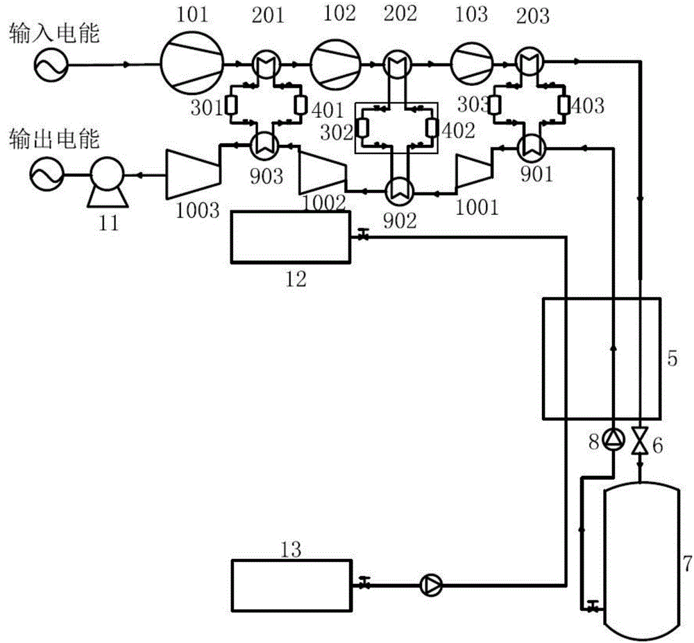
[0032] figure 1It is a structural schematic diagram of the liquefied compressed air energy storage system using liquid cold storage working medium of the present invention; it can be seen from the figure that the liquefied compressed air energy storage system using liquid cold storage working medium provided by the present invention includes: compressor subsystem, cold storage subsystem, Hea...


PUM


Abstract

The invention relates to a liquefied compressed air energy storage system with cold-storage liquid media. The liquefied compressed air energy storage system comprises compressor systems, a cold storage system, a heat storage system, a liquefying system and a turbine power generation system. During energy storage, the multistage compressor system is driven by renewable energy sources, so that compressed air is supercharged to exchange heat with a room-temperature cold-storage liquid medium, the cold quantity stored in the liquid medium is lowered to liquefying temperature, and the compressed air is liquefied through throttling; during energy releasing, the liquid air is supercharged to exchange heat with a high-temperature cold-storage liquid medium, the medium recycles cold energy to give to the liquefying process, and the air is warmed to be vaporized; room-temperature high-pressure air is input into a multi-stage turbine expander for acting, and a power generator is driven to output electric energy; the heat storage system reduces the power consumption of the next stage of compressor, and the stored heat is heated step by step before expansion to raise the intake air temperature; a cold-storage medium with a low freezing point and a high / low boiling point recycles the cold energy of the liquid air, the specific heat capacity of the liquid media is large, and the large-temperature-span heat exchange is realized. The liquefied compressed air energy storage system has the advantages of being simple in structure and stable in performance, can realize integration of energy storage and power generation, and can realize the large-scale grid-connection of renewable energy generation, therefore improving the capacity of a power grid accepting new energy power generation.

Description

technical field [0001] The invention relates to the technical field of renewable energy energy storage, in particular to an energy storage system for liquefied compressed air. Background technique [0002] With the vigorous development of renewable energy, as of the end of 2013, the cumulative total installed capacity of wind power in my country was 91.4GW, and the total installed capacity of solar power was 10GW. It is estimated that by 2015 and 2020, the total installed capacity of wind power in my country will reach 130GW and 200GW respectively, and the total installed capacity of solar power will reach 20GW and 50GW respectively. Corresponding to the vigorous development of renewable energy is the phenomenon of "abandoning wind power and curtailment" caused by the inherent intermittency and instability of renewable energy, which seriously restricts the further large-scale grid connection and safe and stable operation of renewable energy. As a flexible adjustment method,...

Claims


Application Information

Patent Timeline
IPC IPC(8): F28D20/00F01D15/10
CPCY02E60/14
Inventor 罗二仓徐静远公茂琼戴巍王俊杰吴张华胡剑英余国瑶王晓涛张丽敏陈燕燕
Owner TECHNICAL INST OF PHYSICS & CHEMISTRY - CHINESE ACAD OF SCI
Learn More