Eureka AIR delivers breakthrough ideas for toughest innovation challenges, trusted by R&D personnel around the world.

Air pre-heater

An air preheater, flue gas side technology, applied in lighting and heating equipment, combustion methods, indirect carbon dioxide emission reduction, etc., can solve the problems of air leakage of air preheater, accelerated low temperature corrosion, reduction of boiler efficiency, etc., to solve the problem of air leakage problems, increasing economic benefits, and the effect of good sealing effect

Active Publication Date: 2015-11-11
山东泓江智能设备有限公司
View PDF6 Cites 15 Cited by
  • Summary
  • Abstract
  • Description
  • Claims
  • Application Information

AI Technical Summary

Problems solved by technology

After the coal-fired boiler is put into the SCR denitrification system, the ammonium bisulfate scale on the heat transfer element of the air preheater cannot be removed by ordinary steam soot blowing. When the blockage is serious, it has to be shut down for high-pressure water flushing. Ammonium hydrogen scaling is the biggest factor that causes the boiler to fail to operate for a long time
[0006] At the same time, because the air preheater will undergo mushroom-shaped deformation after being heated, a certain gap will be formed between the sealing sheet on the air preheater and the fan-shaped plate. Since the air side of the air preheater is positive pressure airflow, and the flue gas side is negative pressure airflow, Therefore, the air flow on the air side will enter the flue gas side, resulting in the air leakage of the air preheater.
Air leakage will lead to poor thermal conditions of the unit, accelerate low-temperature corrosion, reduce thermal efficiency of the unit, increase fan power consumption, reduce boiler efficiency, and affect the overall operation of the unit

Method used


Image

  • Air pre-heater
  • Air pre-heater
  • Air pre-heater

Examples


Embodiment

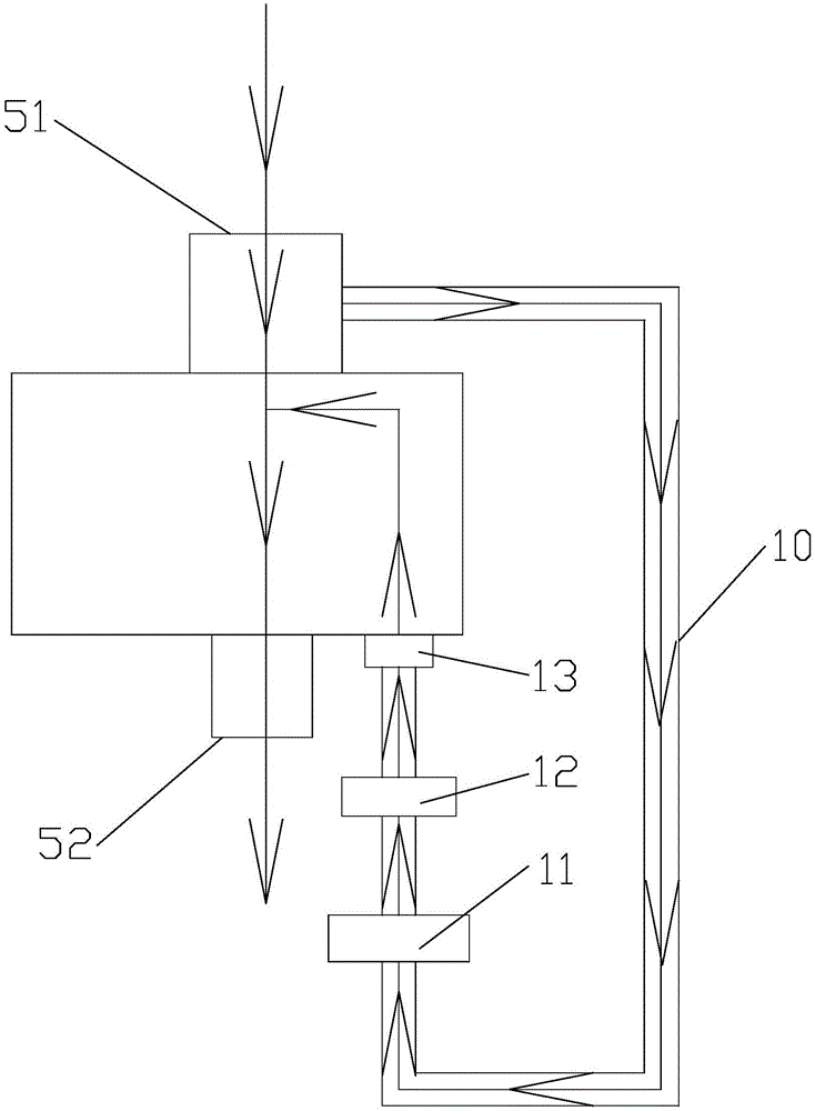
[0023] Embodiment: a kind of air preheater, as Figure 1-2As shown, it includes a rotor 2 with the rotor center tube 1 as the center of the circle. The rotor 2 has a plurality of compartments 3, and heat transfer elements are arranged in the compartments 3. Generally, three pairs of vertically symmetrical sectors are distributed on the upper and lower sides of the compartments 3. Plate 4, wherein two pairs of fan-shaped plates divide the rotor 2 into two semicircles of the same size, thereby dividing the rotor 2 into a smoke side 5 and an air side 6, and the air side 6 is divided into a primary air side by another pair of fan-shaped plates. side 61 and secondary air side 62, there is a casing 7 on the periphery of the rotor 2, and the top of the casing 7 is provided with a flue gas inlet 51 and a primary air outlet corresponding to the flue gas side 5, the primary air side 61, and the secondary air side 62 respectively. 611 and the secondary air outlet 621, the flue gas outlet...


PUM


Abstract

The invention provides an air pre-heater. A temperature increase sector plate is arranged at the position, close to a secondary air side, on a smoke side. The included angle alpha between the temperature increase sector plate and a sector plate closest to the temperature increase sector plate ranges from 7 degrees to 8 degrees. The center angle beta of each separation bin is equal to the included angle alpha. The center angle gamma of the temperature increase sector plate ranges from 9 degrees to 10 degrees. The separation bin between the temperature increase sector plate and the sector plate closest to the temperature increase sector plate is a circulation smoke separation bin. One side of a smoke inlet above the smoke side is communicated with a bypass flue. The bypass flue is sequentially connected with a dust remover, a temperature increase smoke induced draft fan and a temperature increase smoke inlet again, and the temperature increase smoke inlet is communicated with the circulation smoke separation bin. Compared with the prior art, high-temperature smoke is guided to the cold end of the air pre-heater, and when the temperature of the cold end is above 147 DEG C, ammonium bisulfate is scaled and gasified again, and the clogging prevention effect is achieved. Through the action of the temperature increase smoke induced draft fan, positive-pressure smoke flow is formed between the smoke side and an air side, pressure of the positive-pressure smoke flow and pressure of positive-pressure air flow of secondary air restrain mutually, and the air leakage problem is effectively solved.

Description

technical field [0001] The invention relates to the technical field of thermal power generation, in particular to an air preheater capable of solving the problem of ash blocking and air leakage. Background technique [0002] The air preheater is referred to as the air preheater for short. It is generally divided into two types: tubular type and rotary type. At present, the rotary type air preheater includes a rotor centered on the rotor center cylinder. The rotor has multiple compartments. There are heat transfer elements, and there are generally three pairs of fan-shaped plates symmetrical up and down on the upper and lower sides of the rotor compartment. Two pairs of fan-shaped plates divide the rotor into two semicircles of the same size, thereby dividing the rotor into the smoke side and the air side. The air side and the air side are divided into the primary air side and the secondary air side through another pair of fan-shaped plates. The primary air on the primary air...

Claims


Application Information

Patent Timeline
IPC IPC(8): F23L15/00
CPCY02E20/34
Inventor 李为冬
Owner 山东泓江智能设备有限公司
Why Eureka
Eureka Blog
Learn More