
Self-locking control device used for starting electromagnetic valve

A technology for starting electromagnetic valves and control devices, which is applied in the direction of fuel control, charging system, and engine components of turbine/propulsion devices, which can solve problems such as flameout, improve flight safety, and avoid fuel-rich flameout failures.

Inactive Publication Date: 2015-11-11
CHINA HANGFA SOUTH IND CO LTD
View PDF5 Cites 2 Cited by
  • Summary
  • Abstract
  • Description
  • Claims
  • Application Information

AI Technical Summary

Problems solved by technology

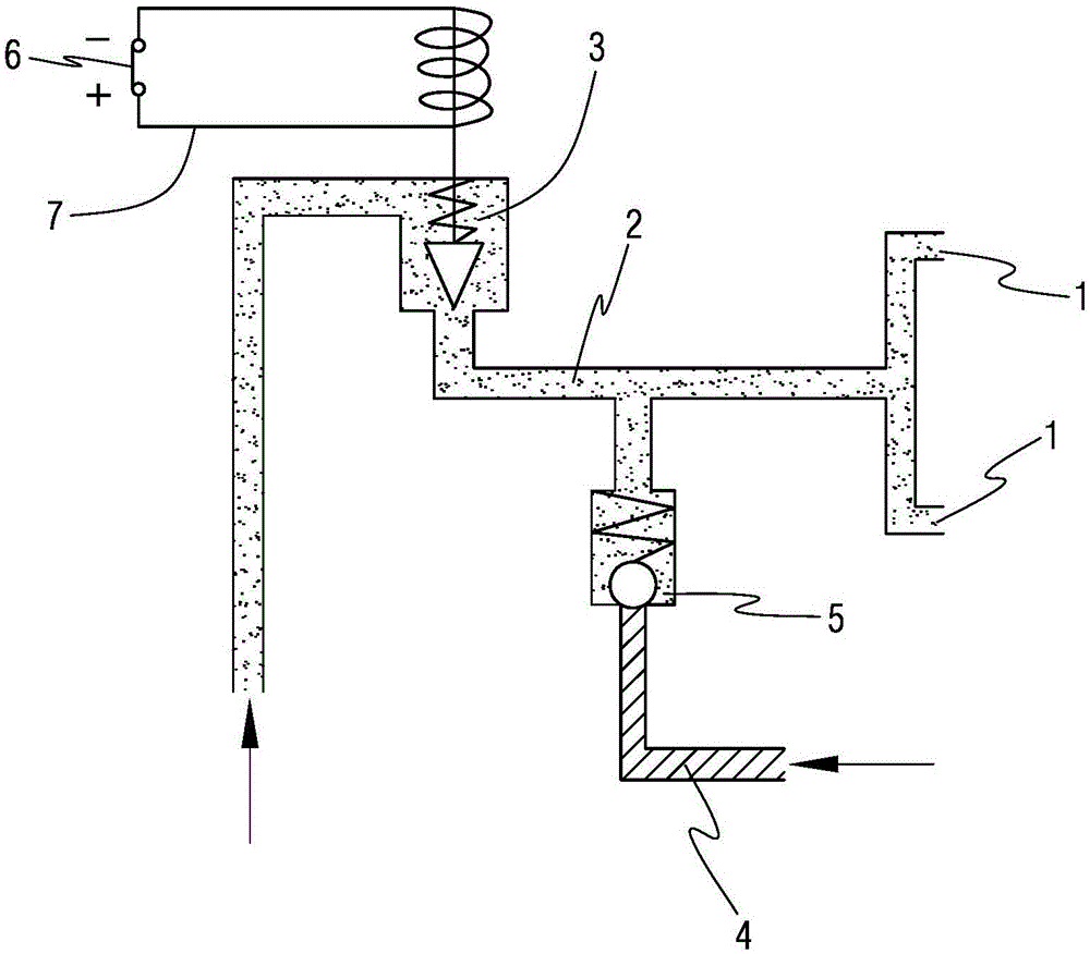
[0006] Specifically, the invention provides a self-locking control device for starting the electromagnetic valve, which is used to solve the problem of flameout caused by mistakenly pressing the start button to turn on the electromagnetic valve to supply fuel again during the normal working process of the turboshaft engine, and to improve flight safety

Method used


Image

  • Self-locking control device used for starting electromagnetic valve
  • Self-locking control device used for starting electromagnetic valve
  • Self-locking control device used for starting electromagnetic valve

Examples


Embodiment Construction

[0018] In order to have a clearer understanding of the technical features, purposes and effects of the invention, the specific implementation of the invention will now be described with reference to the accompanying drawings. Wherein, the same parts adopt the same reference numerals.

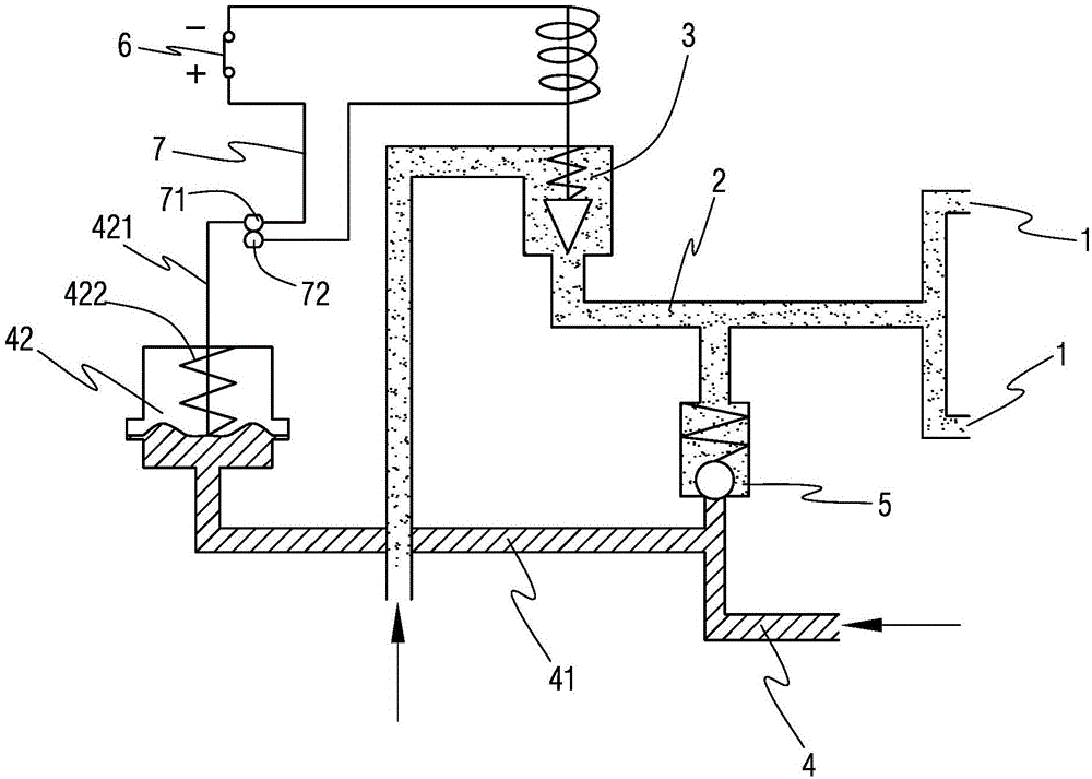
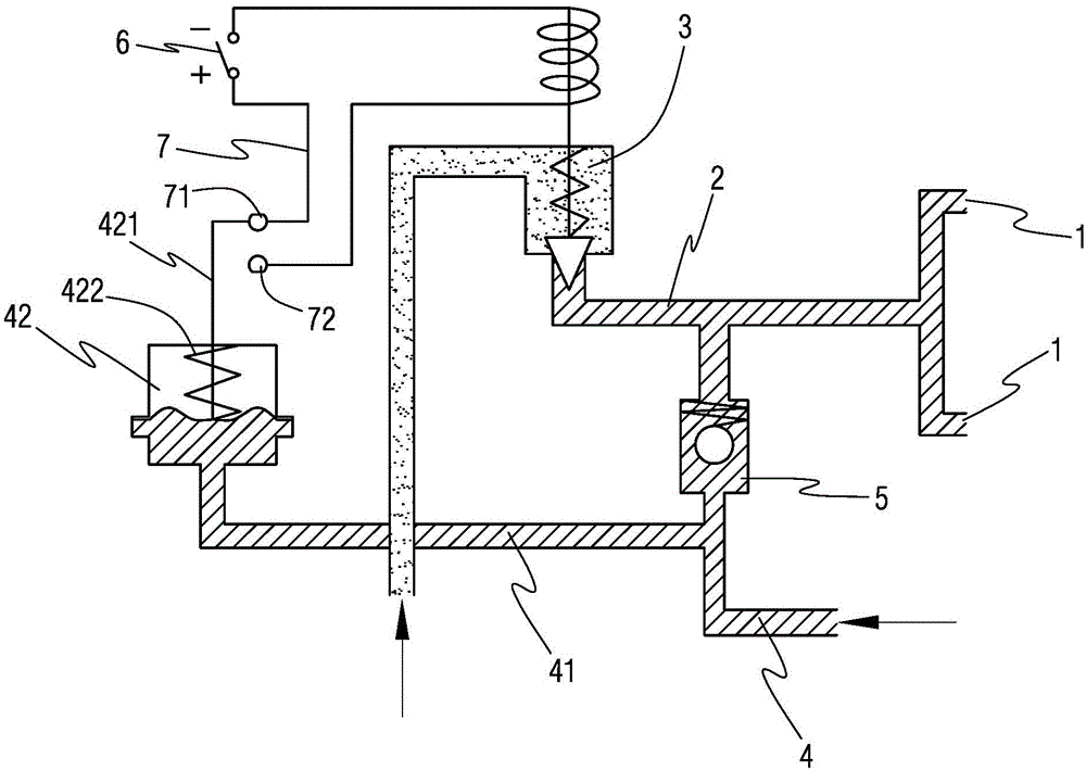
[0019] figure 2 , 3 Shown is a schematic structural diagram of a self-locking control device for starting an electromagnetic valve according to a specific embodiment of the invention, wherein figure 2 Shown is a schematic diagram of the normal starting condition, image 3 Shown is a schematic diagram of normal operation after start-up.

[0020] Such as Figure 2-3 As shown, the self-locking control device for starting the electromagnetic valve of the present invention includes the fuel pipe 2 connected to the starting nozzle 1 of the turboshaft engine, and the fuel pipe 2 is provided with an electromagnetic valve 3 for controlling the on-off of the fuel oil, and the electromagnetic valve 3...


PUM


Abstract

A self-locking control device used for starting an electromagnetic valve comprises a fuel pipe connected with a starting nozzle. The fuel pipe is internally provided with the electromagnetic valve. The fuel pipe is connected with an air inlet pipe. A ball valve is arranged in the air inlet pipe. A control circuit, connected with a power source, of the electromagnetic valve is provided with a start button. The air inlet pipe is connected with a pressure pipe through a bypass. The pressure pipe is provided with a pressure switch controlling the on-off state of the control circuit through the pressure of the air inlet pipe. The pressure switch is additionally arranged on the air inlet pipe and used for automatically cutting off the control circuit of the electromagnetic valve through the pressure of the air inlet pipe after an engine is successfully started, and self-locking is achieved; the system cannot be connected when an aviator presses the start button again, the electromagnetic valve is kept in a closed state, the electromagnetic valve cannot spray oil when started, accordingly, the failure of engine rich extinction is avoided, and flying safety is improved.

Description

technical field [0001] The invention relates to a fuel system of a turboshaft engine in the field of aeroengines, in particular to a control structure of a starting electromagnetic valve of the turboshaft engine, and in particular to a self-locking control device for starting the electromagnetic valve. Background technique [0002] The starting electromagnetic valve of the turboshaft engine is installed on the upper part of the engine compressor casing. During the starting process, the starting electromagnetic valve is controlled by the starting program to energize the electromagnetic valve to ensure the oil supply to the starting nozzle. After starting, the starting nozzle is blown. , to prevent carbon deposition in the nozzle, and close the electromagnetic valve so that it cannot supply oil to the starting nozzle when the engine is working normally. The quality of the starting electromagnetic valve directly affects whether the engine can be started smoothly. [0003] fig...

Claims


Application Information

Patent Timeline
Patent Type & Authority Applications(China)
IPC IPC(8): F02C9/26
Inventor 王星星方春娇蓝华
Owner CHINA HANGFA SOUTH IND CO LTD
Learn More