
Visible grinding machine with automatic fine correction function

A micro-correction, grinding machine technology, applied in the direction of grinding machines, machine tools designed for grinding the rotating surface of workpieces, grinding machine parts, etc. The effect of deviation and quality improvement

Inactive Publication Date: 2015-11-11
SUZHOU RUIQI ELECTRONICS
View PDF10 Cites 0 Cited by
  • Summary
  • Abstract
  • Description
  • Claims
  • Application Information

AI Technical Summary

Problems solved by technology

[0002] In the industrial production process, some parts with inner holes or tubular parts with outer square and inner circle need to grind their inner walls during the application process. However, the existing grinding device cannot perform accurate grinding during the entire grinding process. Positioning and grinding are prone to deviations, which will cause irreversible damage to the parts, make the size of the parts inaccurate, and even cause the parts to be scrapped

Method used


Image

  • Visible grinding machine with automatic fine correction function

Examples


Embodiment

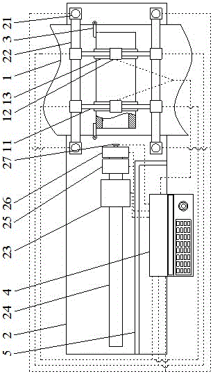
[0015] Such as figure 1 As shown, a visual automatic micro-calibration grinder includes an operating table 1, a grinder table 2 arranged under the operating table 1, and a control system 4 arranged on the grinder table 2; the operating table 1 is an assembly line; both sides of the operation table 1 are provided with rotatable stop bars 3; on both sides of the operation table 1 are installed two Z-axis numerical control slide rails 21 on the grinder table 2; operation table 1 Between the two Z-axis numerical control slide rails 21 corresponding to both sides, an X-axis numerical control slide rail 22 is arranged across the operating table 1; two Y-axis numerical control slide rails 11 are erected between the two X-axis numerical control slide rails 22 The Y-axis numerical control slide rail 11 is provided with a clamping jaw slider 12; the clamping jaw slider 12 is fixed with a clamping jaw 13 for fixing the workpiece; the grinding wheel machine 2 is also fixed with a grinding ...


PUM


Abstract

The invention provides a visible grinding machine with the automatic fine correction function and relates to the field of grinding machines. The problems that when the inner wall of a part is ground through an existing grinding device, localization is inaccurate, deviation is likely to happen, the part is irreversibly damaged, the size of the part is inaccurate, and the part is even scraped are solved. The visible grinding machine with the automatic fine correction function comprises an operating table, a grinding wheel machine table and a control system. Rotary stop rods are arranged on the two sides of the operating table, X-axis, Y-axis and Z-axis sliding rails cross over the operating table, and clamping jaws for fixing workpieces are fixedly arranged below a clamp jaw slider. The grinding wheel machine table is provided with a grinding wheel machine sliding block and a grinding wheel sliding rod. A fine grinding wheel, a rough grinding wheel and an image acquisition device are connected to the right side of the grinding wheel sliding rod. The control system controls the X-axis, Y-axis and Z-axis sliding rails, the clamping jaws, the grinding wheel machine sliding block and a grinding wheel. The image acquisition device is adopted for judging the center position of an inner hole of the part for fine correction, the positions of uneven points are acquired in the grinding process of the part, the grinding time of the uneven points is prolonged, high accuracy is maintained, deviation is avoided, and the part grinding quality is improved.

Description

Technical field [0001] The invention relates to the field of grinders, in particular to a visual automatic micro-correction grinder. Background technique [0002] In the industrial production process, some parts with inner holes or tubular parts with outer square and inner circle need to be polished on the inner wall during the application process. However, the existing polishing device cannot perform precise polishing during the entire polishing process. Positioning and grinding are prone to deviations, which can cause irreversible damage to the parts, make the size of the parts inaccurate, and even cause the parts to be scrapped. Summary of the invention [0003] In order to solve the above technical problems, the present invention provides a visual automatic micro-calibration grinder. [0004] The technical solution adopted by the present invention to solve its technical problems is: a visual automatic micro-calibration grinder, which includes an operating table, a grinding whee...

Claims


Application Information

Patent Timeline
Patent Type & Authority Applications(China)
IPC IPC(8): B24B5/48B24B49/12B24B5/40B24B55/00B24B27/00
CPCB24B5/40B24B5/48B24B27/0076B24B49/12B24B55/00
Inventor 徐静
Owner SUZHOU RUIQI ELECTRONICS
Learn More