One-piece forming method of ultra-slender thin-walled seamless metal pipe

A technology of seamless metal pipe and forming method, applied in the field of metal pipe preparation, can solve the problems of inability to meet application requirements, decrease in the compactness of welded joints, difficult operation and completion of the welding process, etc., and achieve good mechanical processing strength and smooth transition. , the effect of low equipment requirements

Active Publication Date: 2016-09-07
NORTHWEST INSTITUTE FOR NON-FERROUS METAL RESEARCH
View PDF8 Cites 0 Cited by
  • Summary
  • Abstract
  • Description
  • Claims
  • Application Information

AI Technical Summary

Problems solved by technology

[0003] Conventional welding methods between general metals include vacuum brazing, arc welding, gas electric welding, laser welding, electron beam welding, etc. After the ultra-slender thin-walled metal porous tube is prepared, it is welded with the metal dense tube. The special pore structure and slender size requirements will make it difficult to complete the welding process. After welding, there will be holes in the weld seam that are larger than the pore diameter of the metal porous pipe itself, and the compactness of the weld joint will be seriously reduced. The reliable usability of the tube bundle assembly in many occasions has had an adverse effect, especially in some demanding gas / gas separation applications, which simply cannot meet the use requirements proposed by the working condition enterprise, because the metal porous tube itself has Due to the special structure of the metal pipe, after welding with the metal dense pipe by the general conventional method, the weld seam after welding often has a hole diameter larger than the metal porous pipe itself, and the helium leakage rate can only reach 10. -3 ~10 -5 Pa·m 3 / s, there is no way to meet the application requirements at all
[0004] So far, although there have been many related reports on metal welding, most of them are welding between dense materials, and their research fields are completely different. , there are no reports at home and abroad, and no related patent descriptions

Method used


Image

  • One-piece forming method of ultra-slender thin-walled seamless metal pipe
  • One-piece forming method of ultra-slender thin-walled seamless metal pipe
  • One-piece forming method of ultra-slender thin-walled seamless metal pipe

Examples


Embodiment 1

[0033] This embodiment includes the following steps:

[0034]Step 1. Mix the plasticizer and metal powder A uniformly in a mass ratio of 5:50 to obtain a mixture A, and uniformly mix the plasticizer and metal powder B in a mass ratio of 5:50 to obtain a mixture B, and then partly describe The mixture A and part of the mixture B were uniformly mixed at a mass ratio of 1:2 to obtain a mixture C; the metal powder A and the metal powder B were both 316L stainless steel powders, and the average particle diameter of the metal powder A was 22 μm. The average particle diameter of the metal powder B is 34 μm, the mass of the mixture C is 50% of the mass of the mixture A, and the plasticizer is paraffin;

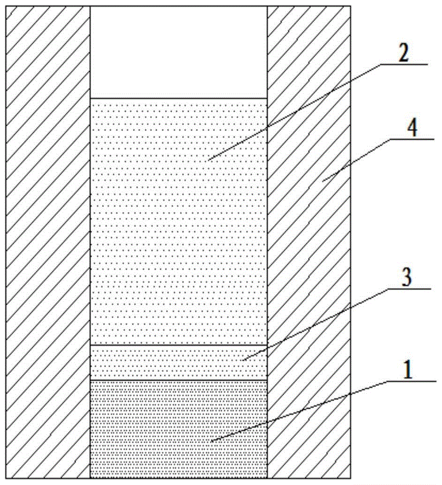
[0035] Step two, such as figure 1 As shown, the remaining mixture A in step 1 is extruded into a billet at a temperature of 40°C to obtain the first billet 1, and the remaining mixture B in step 1 is extruded into a billet at a temperature of 40°C , to obtain the second blank 2, ext...

Embodiment 2

[0042] This embodiment includes the following steps:

[0043] Step 1. Mix the plasticizer and metal powder A uniformly in a mass ratio of 7:50 to obtain a mixture A, and uniformly mix the plasticizer and metal powder B in a mass ratio of 7:50 to obtain a mixture B, and then partly describe The mixture A and part of the mixture B are uniformly mixed at a mass ratio of 1:1 to obtain a mixture C; the metal powder A and the metal powder B are both nickel powders, and the average particle diameter of the metal powder A is 110 μm, so The average particle diameter of the metal powder B is 150 μm, the mass of the mixture C is 35% of the mass of the mixture A, and the plasticizer is paraffin;

[0044] Step two, such as figure 1 As shown, the remaining mixture A in step 1 is extruded into a billet at a temperature of 45°C to obtain the first billet 1, and the remaining mixture B in step 1 is extruded into a billet at a temperature of 45°C , to obtain the second blank 2, extruding the ...

Embodiment 3

[0050] This embodiment includes the following steps:

[0051] Step 1. Mix the plasticizer and metal powder A uniformly in a mass ratio of 6:50 to obtain a mixture A, and uniformly mix the plasticizer and metal powder B in a mass ratio of 6:50 to obtain a mixture B, and then partly describe The mixture A and part of the mixture B are uniformly mixed at a mass ratio of 1:3 to obtain a mixture C; the metal powder A and the metal powder B are both Fe-Al intermetallic compound powders, and the average particle size of the metal powder A is diameter is 80 μm, the average particle diameter of the metal powder B is 130 μm, the mass of the mixture C is 50% of the mass of the mixture A, and the plasticizer is carboxymethyl cellulose;

[0052] Step two, such as figure 1 As shown, the remaining mixture A in step 1 is extruded into a billet at a temperature of 35°C to obtain the first billet 1, and the remaining mixture B in step 1 is extruded into a billet at a temperature of 35°C , to ...


PUM

PropertyMeasurementUnit
thicknessaaaaaaaaaa
lengthaaaaaaaaaa
lengthaaaaaaaaaa

Abstract

The invention discloses an integrated molding method for an ultra-slender thin-wall seamless metal tube. The method includes the steps that (1), a mixture A, a mixture B and a mixture C are prepared; (2), a first blank, a second blank and a third blank are prepared; (3), the first blank, the third blank and the second blank are sequentially placed in an extruding container to be sequentially compressed, and an extruded blank is obtained; the extruded blank is continuously extruded out through a tube extruding nozzle in a powder extrusion molding manner, and green bodies of the metal tube is obtained; and (4), the green bodies of the metal tube are sintered, and the ultra-slender thin-wall seamless metal tubes are obtained. The method is suitable for manufacturing the ultra-slender thin-wall seamless metal tubes made of various metal; each obtained seamless metal tube is formed by connecting a dense metal tube, a porous metal tube and a metal transition tube arranged between the dense metal tube and the porous metal tube in a seamless manner; the seamless metal tube is firm in combination, good in sealing performance, high in mechanical strength, capable of being used in various environments with the high requirement for the extremely high helium leak rate and long in service life.

Description

technical field [0001] The invention belongs to the technical field of metal pipe preparation, and in particular relates to an integral forming method of an ultra-slender thin-walled seamless metal pipe. Background technique [0002] Metal porous tubes are widely used in nuclear industry, energy manufacturing, petrochemical industry, metallurgy, waste gas treatment, It plays an important role in functional areas such as filtration, separation, and fluid distribution in sewage treatment and other fields. In order to increase the filtration area and improve the efficiency of filtration and separation in industrial production, most metal porous tubes are made into a component or tube bundle to replace the original single metal porous tube for filtration and separation. Under the same conditions, this requires the metal porous tube in the component or tube bundle to have a larger aspect ratio size requirement, and due to the improvement of filtration separation conditions, the ...

Claims


Application Information

Patent Timeline
Patent Type & Authority Patents(China)
IPC IPC(8): B22F3/20B22F5/12
Inventor 迟煜頔李纲荆鹏王建李广忠刘海彦沈磊石英
Owner NORTHWEST INSTITUTE FOR NON-FERROUS METAL RESEARCH
Why Eureka
Try Eureka