
Surface-coated cutting tool

一种切削工具、表面包覆的技术,应用在表面包覆切削工具领域,能够解决紧贴强度不充分等问题,达到优异高温强度和高温硬度、提高紧贴强度的效果

Inactive Publication Date: 2015-11-04
MITSUBISHI MATERIALS CORP
View PDF12 Cites 0 Cited by
  • Summary
  • Abstract
  • Description
  • Claims
  • Application Information

AI Technical Summary

Problems solved by technology

There is no problem when using the above-mentioned conventional coated tools for continuous cutting or intermittent cutting of steel and cast iron under normal conditions, but especially when used under high-speed intermittent heavy cutting conditions, the hard coating layer Ti compound layer to form the lower layer with Al 2 o 3 The adhesion strength between the upper layers composed of layers is insufficient, and abnormal damage such as peeling and chipping between the upper layer and the lower layer occurs, thereby reaching the service life in a relatively short period of time. This is the current situation of cutting devices.

Method used


Image

  • Surface-coated cutting tool
  • Surface-coated cutting tool
  • Surface-coated cutting tool

Examples


Embodiment

[0114] As raw material powders, WC powder, TiC powder, ZrC powder, TaC powder, NbC powder, Cr 3 C 2 powder, TiN powder, TaN powder, and Co powder. These raw material powders were blended according to the compounding components shown in Table 1, and after adding wax, they were ball milled and mixed in acetone for 24 hours, and then dried under reduced pressure. Then, pressurize the green compact at a pressure of 98 MPa into a predetermined shape, and vacuum sinter the green compact at a predetermined temperature in the range of 1370 to 1470° C. for 1 hour in a vacuum of 5 Pa. . After sintering, honing was performed on the blade portion with R: 0.07 mm, thereby manufacturing WC-based cemented carbide tool substrates A to E having an insert shape specified in ISO·CNMG120412, respectively.

[0115] In addition, as raw material powders, TiCN (TiC / TiN=50 / 50 by mass ratio) powder, Mo 2 C powder, ZrC powder, NbC powder, TaC powder, WC powder, Co powder, and Ni powder were mixed wit...


PUM

PropertyMeasurementUnit
roughnessaaaaaaaaaa
particle diameteraaaaaaaaaa

Abstract

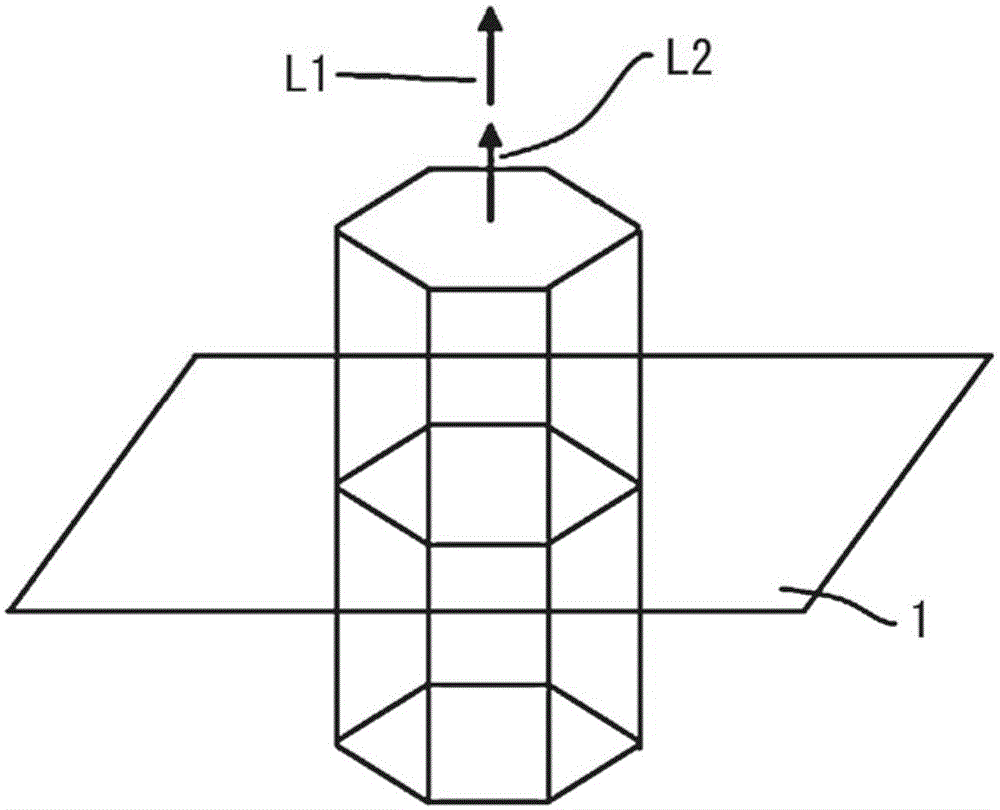
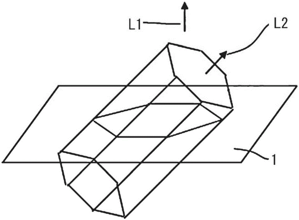
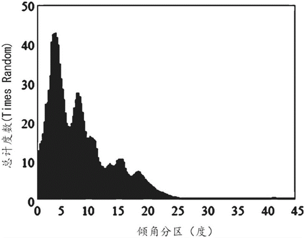
This surface-coated cutting tool is provided with: a lower layer consisting of a Ti compound layer; an intermediate layer consisting of an α-Al2O3 layer; and an upper layer consisting of a Zr-containing α-Al2O3 layer. The uppermost layer of the lower layer contains 0.5 to 3 at% of oxygen. In the frequency distribution made by counting inclination angles between the normal lines to the (0001) planes of Al2O3 grains of the intermediate layer and the normal line to the surface of a tool body, the maximum peak appears in an inclination angle range of 0 to 10 degrees and the ratio of the sum of frequencies falling in this inclination angle range is 50 to 70%. In the frequency distribution made by counting inclination angles between the normal lines to the (0001) planes of Al2O3 grains of the intermediate and upper layers and the normal line to the surface of the tool body, the maximum peak appears in an inclination angle range of 0 to 10 degrees and the ratio of the sum of frequencies falling in the inclination angle range is 75% or more. In at least 70 area% of the grains of the intermediate and upper layers, the inside of each grain is split by one or more crystal lattice interfaces represented by Σ3.

Description

technical field [0001] The present invention relates to a surface-coated cutting tool in which a hard coating layer exhibits excellent peeling resistance and chipping resistance during high-speed intermittent heavy cutting. Specifically, the present invention relates to a cutting process of various steels and cast irons under high-speed intermittent and heavy-duty cutting conditions in which high-speed intermittent and high-impact loads act on the cutting edge. Surface-coated cutting tools that exhibit excellent peeling resistance and chipping resistance, and exhibit excellent long-term wear resistance (hereinafter referred to as coated tools). [0002] This application claims priority based on Patent Application No. 2013-35566 filed in Japan on February 26, 2013 and Patent Application No. 2014-32483 filed in Japan on February 24, 2014, and uses the contents thereof in this specification. Background technique [0003] In the past, the following cladding tools have been know...

Claims


Application Information

Patent Timeline
Patent Type & Authority Applications(China)
IPC IPC(8): B23B27/14
CPCC23C16/56B23B2228/105C23C16/36C23C16/403C23C16/405C23C28/04C23C28/042C23C28/044B23B27/148B23B2224/04B23B2224/28B23B2224/32B23B2224/36C23C30/00
Inventor 奥出正树山口健志长田晃
Owner MITSUBISHI MATERIALS CORP
Learn More