Graphic synchronization device and synchronization method in computer cluster tiled display system
A computer cluster, splicing display technology, applied in the direction of digital output to display equipment, TV system components, image communication, etc., can solve the problems of low reliability, poor anti-interference, high research and development costs, and improve system reliability. , the effect of strong anti-interference ability and low interface cost
- Summary
- Abstract
- Description
- Claims
- Application Information
AI Technical Summary
Problems solved by technology
Method used
Image

Examples
Embodiment 1
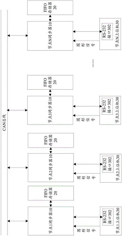
[0038] figure 1 It shows a schematic structural diagram of a graphics synchronization device in a computer cluster splicing display system according to Embodiment 1 of the present invention; figure 1 As shown, it includes: N node synchronizers 10, N FIFO memories 20 and N node host computers 30, the N node synchronizers 10 are connected by CAN bus, and each node synchronizer 10 is connected to each node host computer 30 is connected through RS-232 interface 302, wherein,
[0039] Each node synchronizer 10 is used to receive the graphics signal output by the node host computer 20, and convert the graphics signal into a graphics data stream, write the graphics data stream into the FIFO memory 20 according to the synchronous receiving logic, and according to the synchronous output logic, based on The system clock signal and horizontal and vertical synchronous signals read out the graphic data stream from the FIFO memory 20, and convert the graphic data stream into graphic signal...
Embodiment 2
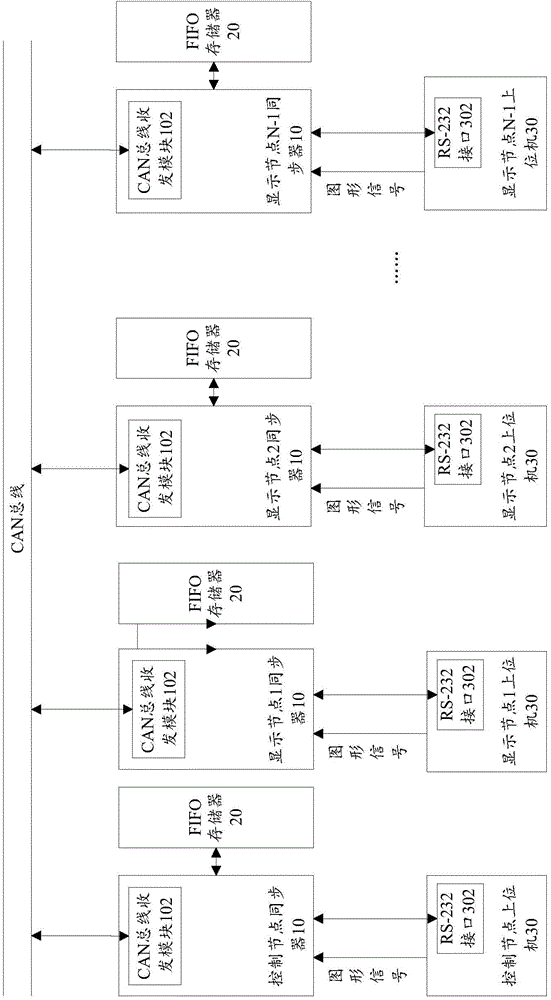
[0048] figure 2 A schematic structural diagram of a graphics synchronization device in a computer cluster splicing display system according to Embodiment 2 of the present invention is shown, as shown in figure 2 As shown, when the node synchronizer 10 is a control node synchronizer, the corresponding node host computer 30 is a control node host computer, and the remaining N-1 node synchronizers 10 are display node synchronizers, and the corresponding node The host computer 10 is a display node host computer, and the display node synchronizer communicates with the control node synchronizer through the CAN bus. After the control node synchronizer 10 receives the start command from the control node host computer 30, when it reaches the sending threshold, it also To broadcast start command to CAN bus.
[0049] Wherein, the node synchronizer 10 is provided with a CAN bus transceiver module 102 for receiving commands from the CAN bus or sending commands to the CAN bus.
[0050] ...
Embodiment 3
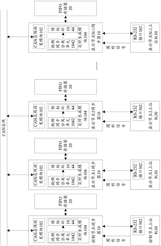
[0052] image 3 A schematic structural diagram of a graphics synchronization device in a computer cluster splicing display system according to Embodiment 3 of the present invention is shown, as shown in image 3 As shown, the clock signal and horizontal and vertical synchronization signals in the system are generated based on the reference video signal by the timing generation module 104 in the node synchronizer 10, wherein the timing generation module 104 includes: a video synchronization separation unit 1042 and a phase-locked loop 1044, of which:
[0053] A video synchronization separation unit 1042, configured to separate a horizontal timing signal and a vertical timing signal of the reference video signal from the reference video signal;
[0054] The phase-locked loop 1044 is used to generate a pixel clock signal and a horizontal and vertical synchronous signal in accordance with the output graphic format whose frequency and phase are locked with the horizontal timing si...
PUM
 Abstract
Description
Claims
Application Information
 - Generate Ideas
- Intellectual Property
- Life Sciences
- Materials
- Tech Scout
- Unparalleled Data Quality
- Higher Quality Content
- 60% Fewer Hallucinations
Browse by: Latest US Patents, China's latest patents, Technical Efficacy Thesaurus, Application Domain, Technology Topic, Popular Technical Reports.
© 2025 PatSnap. All rights reserved.Legal|Privacy policy|Modern Slavery Act Transparency Statement|Sitemap|About US| Contact US: help@patsnap.com