
Main shaft built-in mechanical on-line dynamic balancing system

A mechanical, dynamic unbalanced technology, applied in static/dynamic balance testing, measuring device, machine/structural component testing, etc. Due to the complex structure of the dynamic balancing device and the small space of the spindle process hole, the effects of compact structure, low loss and comprehensive functions are achieved.

Active Publication Date: 2015-11-04
SHENYANG JIANZHU UNIVERSITY
View PDF12 Cites 12 Cited by
  • Summary
  • Abstract
  • Description
  • Claims
  • Application Information

AI Technical Summary

Problems solved by technology

However, the speed of the high-speed CNC machine tool spindle is mostly tens of thousands of revolutions, and some even reach hundreds of thousands of revolutions, and the power is relatively large.
The built-in dynamic balancing device needs to be placed inside the main shaft to rotate with the main shaft, so the response speed, signal transmission, power supply and other aspects of the measurement and control system are difficult to meet the needs of the dynamic balancing device
Furthermore, due to the narrow space of the general spindle process hole and the complex structure of the mechanical dynamic balancing device, how to fix the dynamic balancing device in a small space and arrange the internal structure of the device is challenging

Method used


Image

  • Main shaft built-in mechanical on-line dynamic balancing system
  • Main shaft built-in mechanical on-line dynamic balancing system
  • Main shaft built-in mechanical on-line dynamic balancing system

Examples


Embodiment

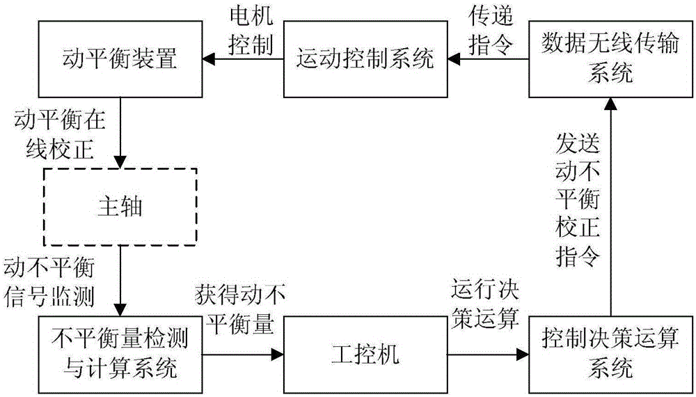
[0063] Example: such as figure 1 Shown, including dynamic balance device, motion control system, data wireless transmission system, dynamic unbalance detection and calculation system, control decision calculation system and industrial computer;

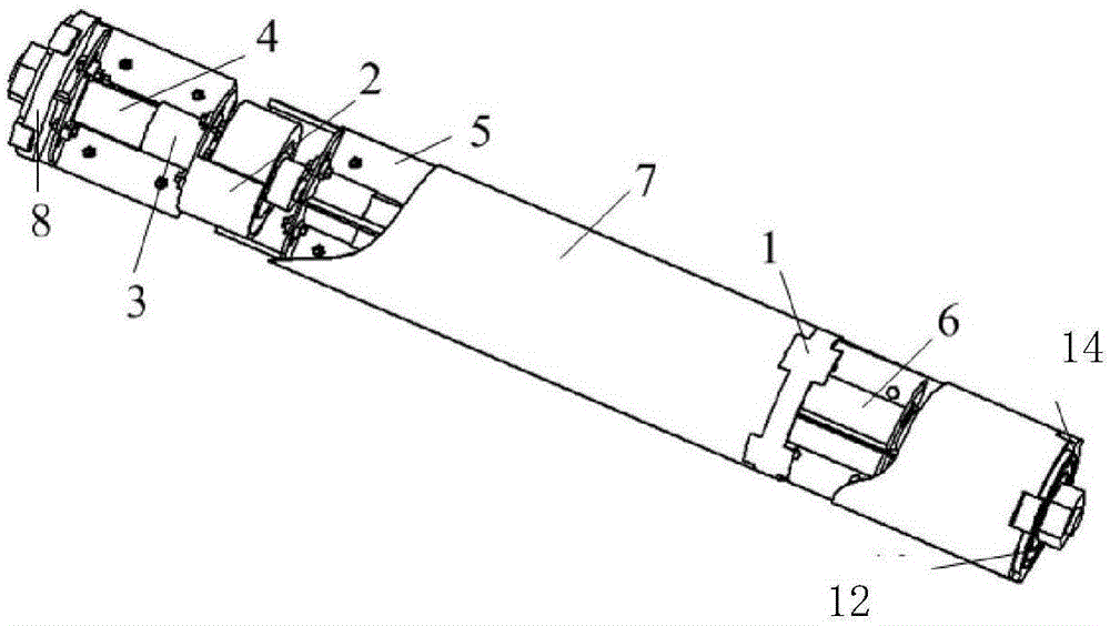
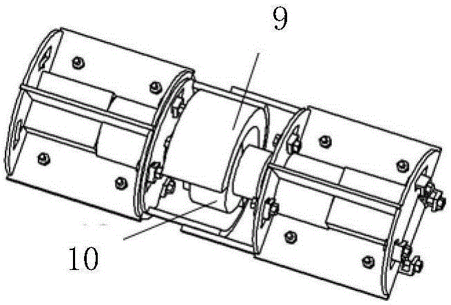
[0064] The dynamic balancing device is placed in the main shaft 19. When working, the mass eccentricity is generated by the two sets of concentric and parallel mass blocks. When the main shaft 19 rotates, the dynamic unbalance force generated by the mass eccentricity is at the same position as that of the main shaft 19 itself. The dynamic balance force of equal magnitude and opposite direction can perform online correction of the dynamic imbalance of the spindle 19;

[0065] The dynamic unbalance detection and calculation system detects the unbalance signal of the spindle, analyzes the characteristics of the spindle dynamic unbalance according to the signal, and calculates the equivalent centrifugal force of the spindle dynamic unbalance an...


PUM


Abstract

The invention provides a main shaft built-in mechanical on-line dynamic balancing system and belongs to the high-speed main shaft on-line dynamic balancing technology field. The main shaft built-in mechanical on-line dynamic balancing system comprises a dynamic balancing device, a movement control system, a data wireless transmission system, a dynamic unbalancing detection calculation system and a control decision operation system. The dynamic balancing device is placed in a main shaft. The dynamic unbalancing detection calculation system detects an unbalancing signal of the main shaft, and analyzes and calculates a main shaft dynamic unbalancing equivalent centrifugal force, a vector direction of the force and a position of the force. The control decision operation system carries out equivalent decomposition of the equivalent centrifugal force to two dynamic unbalancing adjustment planes, calculates a dynamic unbalancing equivalent centrifugal force of each plane, and makes a mass distribution strategy of each mass block group. The data wireless transmission system receives and transmits a dynamic unbalancing correction instruction. The movement control system is installed in a control cavity of the dynamic balancing device, receives the dynamic unbalancing correction instruction and controls rotation of a motor in the dynamic balancing device. The main shaft built-in mechanical on-line dynamic balancing system is suitable for various main shaft operation conditions, and achieves main shaft dynamic unbalancing state on-line correction.

Description

Technical field [0001] The invention belongs to the technical field of high-speed spindle online dynamic balancing, and particularly relates to a mechanical online dynamic balancing system with a built-in spindle. Background technique [0002] High-speed CNC machine tools are one of the technical foundations and development directions of the equipment manufacturing industry. The technical level of high-speed CNC machine tools is a sign that measures the level of a country's manufacturing industry. The main shaft is one of the most critical parts of all rotating CNC machine tools, and its performance has a vital influence on the machining accuracy and reliability of the entire machine tool. Unbalance of rotation is one of the main factors affecting the rotation accuracy of the spindle. The realization of dynamic balance on the spindle has become an indispensable key technology. It is the ultimate goal of improving the rotation accuracy, reliability and service life of the spindle....

Claims


Application Information

Patent Timeline
IPC IPC(8): G01M1/38
Inventor 吴玉厚张珂邓华波张丽秀石怀涛范丽婷王展李桐张驰宇
Owner SHENYANG JIANZHU UNIVERSITY
Learn More