
a gas combustion chamber

A combustion chamber and combustion chamber technology, which is applied in the direction of using a variety of fuel combustion, combustion types, combustion equipment, etc., can solve the problems of short gas residence time, high energy consumption, low combustion rate, etc., to save purification treatment costs, The overall structure is simple and the effect of increasing the contact time

Active Publication Date: 2018-10-16
嘉善凝溪建设有限公司
View PDF12 Cites 0 Cited by
  • Summary
  • Abstract
  • Description
  • Claims
  • Application Information

AI Technical Summary

Problems solved by technology

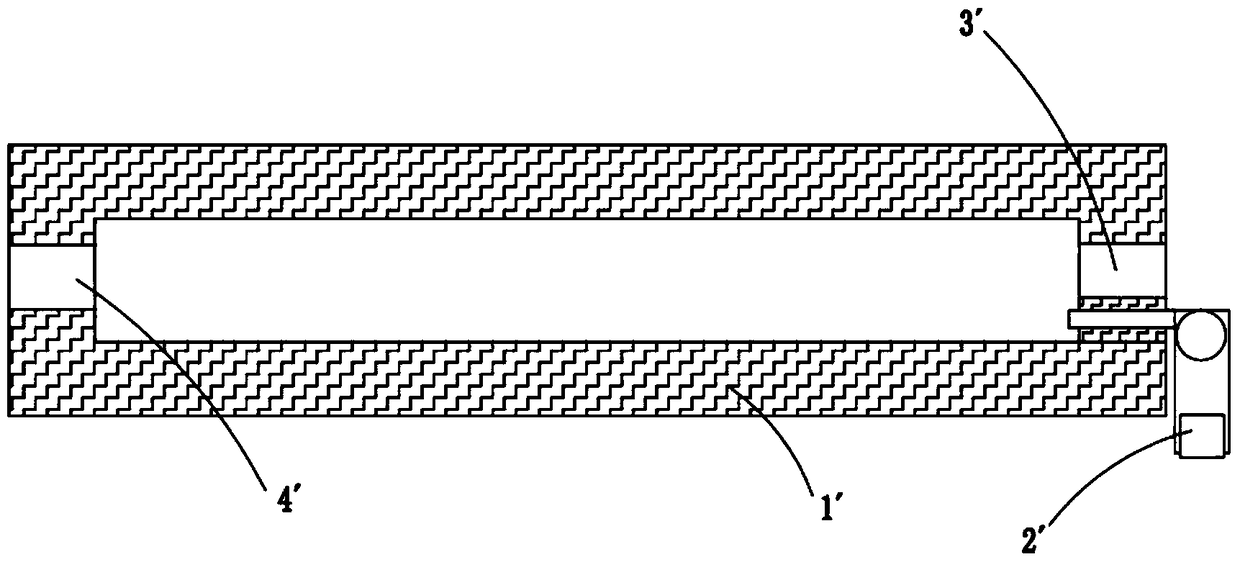
While traditional gas combustors, such as figure 1 As shown, it mainly includes a shell 1' and a burner 2'. The burner 2' is set on the same side as the gas inlet 3', and is set opposite to the combustion chamber gas injection port 4'. The gas enters the combustion chamber and burns through the burner. , the high-temperature flue gas produced is sprayed by the gas injection port 4' to provide heat for heating the furnace, but because the burner 2' is set opposite to the gas injection port 4', and there is no barrier in the combustion chamber, the residence time of the gas in the combustion chamber is short, and The contact area between the burner nozzle and the gas is limited, resulting in insufficient combustion and low combustion rate. Among them, part of the gas is burned to produce high-temperature flue gas, and the other part of unburned gas is ejected from the gas nozzle along with the high-temperature flue gas flow, which is the heating furnace. For heat supply, the flue gas after heat exchange needs to be purified before it can be discharged up to the standard, which increases the flue gas purification process, which is costly and consumes a lot of energy

Method used


Image

  • a gas combustion chamber
  • a gas combustion chamber
  • a gas combustion chamber

Examples


Embodiment 1

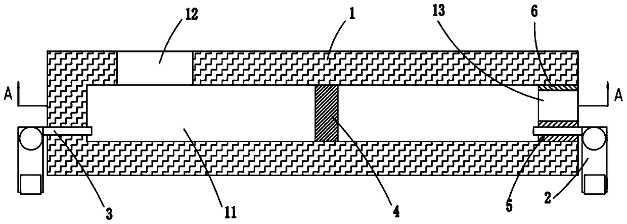
[0022] The present invention provides a gas combustion chamber, such as figure 2 As shown, it includes a casing 1 with a combustion chamber 11 inside. The casing 1 can be designed as a cuboid, cube or other shapes as a whole. Air inlet 13, wherein, the inner wall of gas inlet 13 is provided with a refractory layer 6, which improves the fire resistance and service life of the gas conduit. The left and right sides of the casing 1 are respectively provided with a first burner 2 and a second burner 3 communicating with the combustion chamber 11. The first burner 2 and the second burner 3 are arranged horizontally opposite each other. The first burner 2 It is arranged on the same side as the gas inlet 13 and is located below the gas inlet 13 . A heat insulating block 5 is arranged between the first burner 2 and the gas inlet 13 to prevent the high temperature generated by the second burner 3 from damaging the gas inlet pipe.

[0023] In order to prevent the two burners from burn...

Embodiment 2

[0027] Such as Figure 4 As shown, the components that are the same as or corresponding to those in the first embodiment are marked with the corresponding reference numerals in the first embodiment. For the sake of simplicity, only the differences from the first embodiment will be described below. This embodiment two and figure 2 The difference of the first shown embodiment is that the number of air barriers 4 in this embodiment is more than two, such as two, three or four, which are set according to the length of the combustion chamber 11 and the actual working requirements, and Adjacent gas-blocking walls 4 are arranged staggered up and down on the inner wall of housing 1, so that the high-temperature flue gas and incompletely burned gas generated by the combustion of the gas through the first burner 2 run along the surface of the gas-blocking wall 4 and the ends of the gas-blocking wall 4 The high-temperature flue gas channel 14 flows between the upper part and the inner ...


PUM


Abstract

The invention relates to a gas combustor which comprises a housing. A combustion chamber is formed inside the housing. The housing is square and is provided with an air nozzle and a fuel gas inlet which are communicated with the combustion chamber. A first burner and a second burner are arranged on the left and right sides of the housing respectively. The first burner is arranged on the same side with the fuel gas inlet and is located below the fuel gas inlet. At least one air retaining wall for separating the first burner from the second burner is arranged in the combustion chamber, and the air retaining walls are lower than the combustion chamber. A high temperature fuel gas flue is reserved between the ends of the air retaining walls and the inner walls of the housing. Two-stage combustion is adopted, so that it is guaranteed that fuel gas burns sufficiently. Due to cooperation of the two burners and the air retaining walls, the flowing path of fuel gas in the combustion chamber is changed so as to prolong the residence time of fuel gas in the combustion chamber; the contact time of fuel gas and flame nozzles of the two burners is prolonged, so that the combustion ratio is high, and the cost for later purification treatment is reduced. The gas combustor is simple in overall structure and environmentally friendly, and saves energy.

Description

Technical field: [0001] The invention relates to the technical field of stove manufacturing, and more specifically relates to a gas combustion chamber. Background technique: [0002] The gas combustion chamber is a device that generates high-temperature flue gas by burning combustible gases such as acetylene, natural gas or propane. It is also a key device for the heat source of the hot blast stove. The combustion efficiency of the gas in the combustion chamber is directly related to the heat treatment effect of the hot blast stove. While traditional gas combustors, such as figure 1 As shown, it mainly includes a shell 1' and a burner 2'. The burner 2' is set on the same side as the gas inlet 3', and is set opposite to the combustion chamber gas injection port 4'. The gas enters the combustion chamber and burns through the burner. , the high-temperature flue gas produced is sprayed by the gas injection port 4' to provide heat for heating the furnace, but because the burner ...

Claims


Application Information

Patent Timeline
Patent Type & Authority Patents(China)
IPC IPC(8): F23C5/08
Inventor 沈润良
Owner 嘉善凝溪建设有限公司
Learn More