
On-line adjustable fuel gas generator adopting jet flow collision combustion mode

A technology of gas generator and combustion method, which is applied in jet propulsion devices, machines/engines, rocket engine devices, etc., and can solve problems such as difficult to simulate changes in air flow environment of aircraft, long combustion chamber length of diffusion combustion, difficult outlet flow and Mach number, etc. problem, to achieve the effect of good combustion efficiency, good flame stability, and uniform gas flow field

Active Publication Date: 2015-11-04
PLA PEOPLES LIBERATION ARMY OF CHINA STRATEGIC SUPPORT FORCE AEROSPACE ENG UNIV
View PDF5 Cites 12 Cited by
  • Summary
  • Abstract
  • Description
  • Claims
  • Application Information

AI Technical Summary

Problems solved by technology

The flame tube combustion chamber of an aero-engine has a complex structure and difficult organization of the working process, so it is seldom used in this type of field
The combustion organization technology of fuel injection in the head of the liquid rocket engine is adopted, and the structure is relatively simple, but the fuel is injected, atomized, and evaporated in the combustion chamber, and the diffusion combustion requires a long length of the combustion chamber, thereby increasing the cooling area of ​​the combustion chamber , under long-term working conditions, a large-scale cooling channel needs to be arranged on the body of the combustion chamber; the outlet throat cannot be adjusted, and it is difficult to adjust the outlet flow and Mach number during the working process, which makes the gas in the form of a heater generate It is difficult for the generator to simulate the airflow environment changes of the aircraft under variable working conditions, and it is also difficult for the pipeline rocket ramjet burner generator to adapt to the parameter changes of the ram air and organize the afterburning process reasonably

Method used


Image

  • On-line adjustable fuel gas generator adopting jet flow collision combustion mode
  • On-line adjustable fuel gas generator adopting jet flow collision combustion mode
  • On-line adjustable fuel gas generator adopting jet flow collision combustion mode

Examples


Embodiment Construction

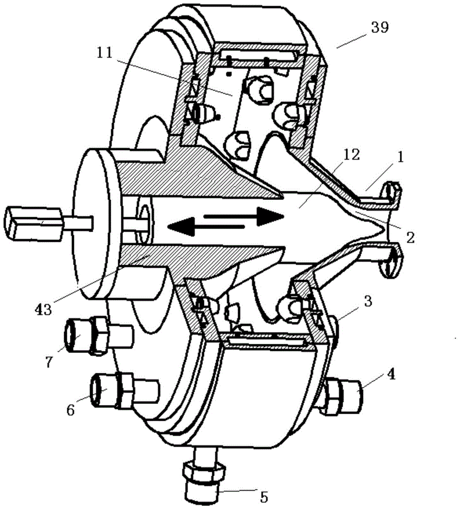
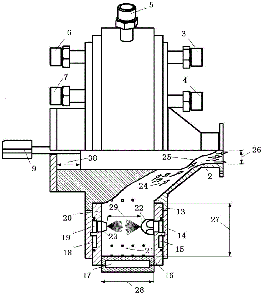
[0022] Such as figure 1 , figure 2 As shown, in the annular groove combustion chamber 11 formed by the combination of the front injection panel 20, the rear injection panel 13, and the body cooling panel, the umbrella-shaped airflow ejected from the oxidizer nozzle 23 is in phase with the spray spray from the fuel nozzle 22. collide, carry out mixed combustion, and form a stationary aerodynamic vortex structure in the combustion chamber 11. The length dimension 28 of the combustion chamber is determined according to the nozzle interaction distance 39 determined by the jet penetration length of the nozzle, so as to ensure the effective organization of the collision jet spray combustion. The radial size 27 of the combustion chamber is determined according to the flow power of the combustion chamber and the installation conditions.

[0023] Cooling liquid is injected into the body cooling injection panel 16 to perform liquid film regenerative cooling on the body, and the cooli...


PUM


Abstract

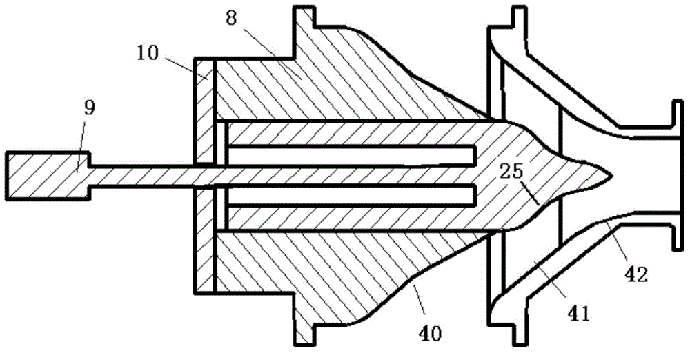
The invention discloses an on-line adjustable fuel gas generator adopting a jet flow collision combustion mode. The on-line adjustable fuel gas generator is composed of a circular groove combustion chamber, a contraction section and an adjusting plug-cone component, wherein an adjusting plug cone is located on the head portion of the fuel gas generator, and is coaxially installed with the contraction section; the circular groove combustion chamber is formed by combining a front jet panel, a rear jet panel and a body cooling panel; the adjusting plug-cone component is composed of the adjusting plug cone, an action sleeve and a fixed disk; and the adjusting plug cone can move back and forth in the action sleeve, and the adjusting plug cone and the contraction section surface are designed in a matched manner. The on-line adjustable fuel gas generator adopting the jet flow collision combustion mode has the beneficial effects that the structure is compact, the length of the combustion chamber is short, the requirements of the structural size and the cooling area of the combustion chamber are greatly reduced, the fuel gas generator can be suitable for on-line adjustment on various combustion conditions of fuel gas generators of a ground testing system in the aerospace industry, the excellent flame stabilization and the fuel gas mixing ability are achieved, and the exit flow field is uniform.

Description

technical field [0001] The invention relates to a method of organizing combustion by means of jet collision, so as to facilitate the atomization, blending and high efficiency and stability of combustion of liquid fuel, and reduce the structural size and cooling area requirements of the combustion chamber. The multi-working condition gas generator adopts movable plug cone to adjust the throat area on-line for cooling. Background technique [0002] The gas generator is widely used in the aerospace field. It burns the oxidant and fuel according to the mixing ratio required by the design to obtain the gas required by certain pressure, temperature, flow and velocity parameters to achieve specific purposes, such as generating ejection Airflow, drive turbine, generate ejection airflow, etc. The application of gas generators in the field of ramjet engines is mainly manifested in two categories: one is the combustion heater used to heat air in the ground test system of ramjet engine...

Claims


Application Information

Patent Timeline
IPC IPC(8): F02K9/52
Inventor 席文雄文明赵文涛李兰
Owner PLA PEOPLES LIBERATION ARMY OF CHINA STRATEGIC SUPPORT FORCE AEROSPACE ENG UNIV
Learn More