Centering clamping device

A technology of clamping device and centering shaft, which is applied in the direction of clamping device, positioning device, clamping, etc., can solve the problems of poor centering effect and achieve high precision and good centering effect

Active Publication Date: 2015-11-04
宿迁天成锋精机股份有限公司
View PDF5 Cites 5 Cited by
  • Summary
  • Abstract
  • Description
  • Claims
  • Application Information

AI Technical Summary

Problems solved by technology

[0003] The purpose of the present invention is to provide a new type of centering clamping device with better centering effect in view of the defect of poor centering effect existing in the existing centering clamping device

Method used


Image

  • Centering clamping device
  • Centering clamping device

Examples


specific Embodiment approach

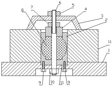
[0010] combined with figure 1 , the specific embodiment of the present invention is:

[0011] A centering clamping device according to the present invention includes a base (1). The base (1) is not only the basis for the installation and positioning of the device, but also a bridge connecting the entire device with machine tools or other equipment. , on the base (1), it is necessary to reserve an installation position connected to the machine tool and connecting devices such as bolt holes, and a centering shaft (2) is installed on the base (1), and the centering shaft (2 ) is shaped on a large hole (12) in the middle of the large hole (12), and a section of annular waist hole (13) with a diameter greater than the diameter of the large hole (12) is made at the waist position of the large hole (12). The mandrel (2) has a thinner wall thickness, and a small through hole (14) is formed at the bottom of the large hole (12). The centering shaft (2) is fixed on the base (1) by...


PUM


Abstract

The invention discloses a centering clamping device and belongs to the technical field of machine tool clamps. The centering clamping device mainly comprises a centering shaft installed on a base. A large hole is formed in the middle of the centering shaft. An annular waist hole with a larger diameter is formed in the waist portion of the large hole, so that the centering shaft wall at the portion is thinner. By means of the method of pouring hydraulic media into the internal space of the centering shaft and using a piston for pressurizing the hydraulic media for expansion to enable the centering shaft wall of the annular waist hole to expand outwards, the workpiece centering purpose is achieved. The centering clamping device has the beneficial effects of being good in centering effect and high in precision.

Description

technical field [0001] The invention relates to a centering clamping device, which belongs to the technical field of machine tool fixtures. Background technique [0002] In the process of machining production, in order to ensure the accuracy of processed products, some workpieces often need to be centered and clamped, and a special centering clamping device is generally used for centering and clamping the workpiece. Although the existing centering clamping device is not They are all the same, but a centering shaft is generally used. The outer circle size of the centering shaft is manufactured according to the inner hole size of the workpiece with a small clearance and tolerance size. Obviously, due to the existence of manufacturing tolerances and installation tolerances, fixed Heart effect is poor. Contents of the invention [0003] The object of the present invention is to provide a new type of centering clamping device with better centering effect for ...

Claims


Application Information

Patent Timeline
Patent Type & Authority Applications(China)
IPC IPC(8): B23Q3/06
CPCB23Q3/06B23Q2703/02
Inventor 孙生强
Owner 宿迁天成锋精机股份有限公司
Why Eureka
Try Eureka