Concentric chamfering device

A chamfering device and chamfering technology, which are applied in the field of chamfering equipment, can solve the problem that long hole chamfering is difficult to ensure concentricity, etc., and achieve the effect of strong applicability and simple operation.

Active Publication Date: 2017-01-04
WENLING MINGHUA GEAR
View PDF6 Cites 0 Cited by
  • Summary
  • Abstract
  • Description
  • Claims
  • Application Information

AI Technical Summary

Problems solved by technology

[0004] The present invention is to provide a concentric chamfering device, which solves the problem that the chamfering of long holes is difficult to ensure concentricity in the prior art

Method used


Image

  • Concentric chamfering device
  • Concentric chamfering device

Examples


Embodiment Construction

[0026] In order to make the technical means, creative features, goals and effects achieved by the present invention easy to understand, the present invention will be further described below in conjunction with specific illustrations.

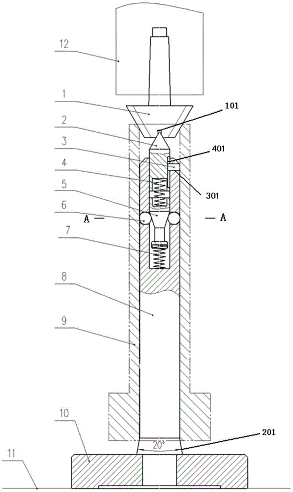
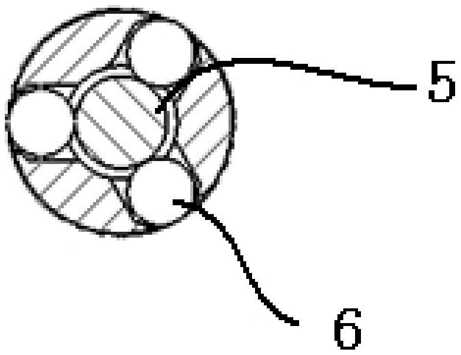
[0027] see Figure 1-2 shown. in figure 1 is the sectional view of the concentric chamfering device; figure 2 for figure 1 Middle A-A sectional view.

[0028] The device is a chamfering tool designed by skillfully using the self-centering principle of the cone, which greatly reduces the processing cost, and its principle is scalable.

[0029] The device is placed on a table 11. The device includes a base 10 for a fixing device; a chamfering countersink 1 is used for turning workpieces, and the chamfering countersinking 1 is arranged on the machine tool spindle 12; The center hole 101 of the corner spot facing drill 1 and the floating top 2 realize the positioning and concentricity of the tool and the device; The inner cavity (not shown i...


PUM


Abstract

The invention relates to a concentric chamfering device which comprises a base and a chamfering counter bit, wherein the base is used for fixing the device, and the chamfering counter bit is used for turning workpieces and arranged on a machine tool spindle; a center hole is formed in the bottom of the chamfering counter bit; the base is provided with a concentric cylinder, and the concentric cylinder and the chamfering counter bit are concentric; the upper end of the concentric cylinder is provided with an inner cavity, and a floating tip is placed in the inner cavity; the floating tip makes contact with the bottom of the inner cavity through a first elastomer to achieve elastic movement; the bottom of the concentric cylinder is provided with a frustum. The concentric chamfering device is high in applicability, capable of being machined on a common drilling machine and easy to operate. The coaxiality between a chamfer and an inner hole can be kept within phi 0.15, and the use requirements of the product are satisfied; locating and concentricity between a tool and the device are achieved by utilizing the center hole of the chamfering counter bit and the floating tip; the elastic force difference of springs is utilized to move down the frustum, and therefore centering of a steel ball is achieved.

Description

technical field [0001] The invention relates to the technical field of chamfering equipment, in particular to a concentric chamfering device. Background technique [0002] There is a long-shaft hollow part in the tractor gearbox. Because the center passes through the transmission shaft part, the middle hole in the hollow part is required to meet a certain coaxiality requirement to ensure that no interference occurs during assembly. And this long-axis hollow part generally all is to process the hole in the middle earlier during processing, and then process the external dimensions. Therefore, the chamfering at both ends of the hole and the concentricity of the long hole become more important after hole machining. [0003] In view of this, it is necessary to study a chamfering device to prepare parts with high coaxiality between the chamfer and the inner hole. Contents of the invention [0004] The invention aims to provide a concentric chamfering device, which solves the p...

Claims


Application Information

Patent Timeline
Patent Type & Authority Patents(China)
IPC IPC(8): B23D79/00
Inventor 戴捷汤永刚
Owner WENLING MINGHUA GEAR
Why Eureka
Try Eureka