Self-centering micro drill bit without chisel edge

A self-centering, no chisel edge technology, used in repairing drills, drilling tool accessories, drilling/drilling equipment, etc., can solve problems such as reduced positioning accuracy, low service life, rough hole walls, etc., to improve the hole position. Accuracy and hole type accuracy, reduce wear and breakage, improve the effect of stress conditions

Active Publication Date: 2015-11-11
BEIJING INSTITUTE OF TECHNOLOGYGY
View PDF8 Cites 3 Cited by
  • Summary
  • Abstract
  • Description
  • Claims
  • Application Information

AI Technical Summary

Problems solved by technology

Due to the increase of drill core thickness, the length of the chisel edge is increased, which reduces the centering performance of the micro drill
When micro-drilling into the drill, the longer chisel edge makes the drill point swim on the surface of the workpiece, which reduces the positioning accuracy of the hole and increases the roundness error of the entrance
[0005] (2) Large axial drilling force
[0006] (3) The processing quality of the hole is poor
When the front angle of the drill tip is small, it is beneficial to centering when entering the drill, but the chip width generated during the drilling process is large, it is not easy to remove the chip, the friction between the chip and the hole wall is intensified, the hole wall is rough, and the hole exit Easy to form burrs
[0007] Due to the above defects in the existing micro-drills, the micro-drills are easily broken during the micro-drilling process, the service life is low, and the processing quality of the holes is poor, which seriously hinders the improvement of the processing quality and production efficiency of the micro-drilling process.

Method used


Image

  • Self-centering micro drill bit without chisel edge
  • Self-centering micro drill bit without chisel edge
  • Self-centering micro drill bit without chisel edge

Examples


Embodiment Construction

[0019] The present invention will be further described in detail below in conjunction with the accompanying drawings and embodiments.

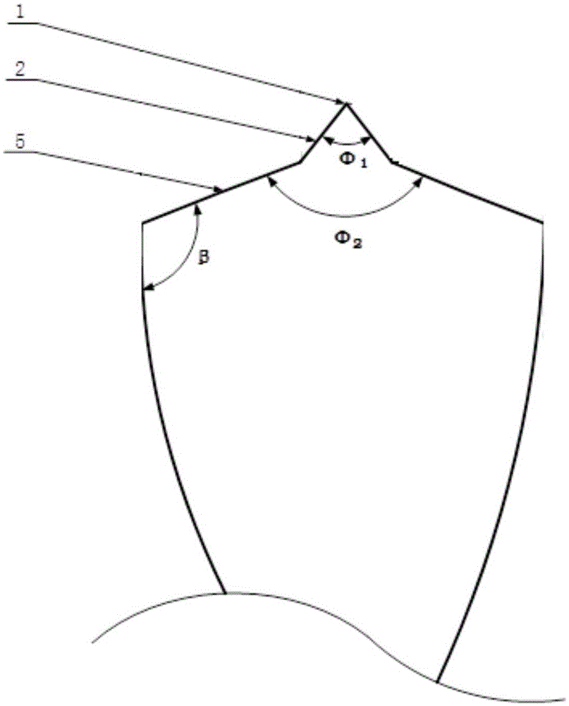
[0020] This embodiment provides a self-centering micro-drill without a chisel edge, and the diameter range of the micro-drill that can be processed is tiny holes in between. See attached figure 1 , 2 , the chisel-free self-centering micro-drill has a two-stage drill point structure, including: drill body 7, a primary drill point and a secondary drill point; wherein the primary drill point starts from the drill body 7, and the secondary drill point starts from The top of the first-level drill point, and the apex of the second-level drill point is the drill core point 1. The drill body 7, the primary drill point and the secondary drill point are all located on the same axis.

[0021] The primary drill tip includes: two outer edges 5 and two outer edge flanks 6; the secondary drill tip includes: drill core tip 1, two inner edges 2, two inner...


PUM


Abstract

The invention relates to the technical field of the machining, in particular to a micro-drilling tool. According to the technical scheme of a self-centering micro drill bit without a chisel edge, the self-centering micro drill bit without the chisel edge comprises a drill bit body, a first-level drill point and a second-level drill point; the first-level drill point starts from the drill bit body; the second-level drill point starts from the top of the first-level drill point; a drill core point is the apex of the second-level drill point and formed by grinding inner edge rake faces on the two sides of the second-level drill point; the drill core point is not provided with the chisel edge. According to the self-centering micro drill bit without the chisel edge, due to the fact that the original chisel edge structure of a common twist drill is omitted from the second-level drill point, so that on the one hand, the centering effect of the micro drill bit is improved, the deflection of the drill points is effectively avoided when drilling is carried out, and hole site precision and hole type precision of drilled holes are increased; on the other hand, cutting resistance is effectively reduced in the drilling process, stressed conditions of the micro drill bit are improved, abrasion and breakage of the micro drill bit are reduced, and the service life of the micro drill bit is prolonged.

Description

technical field [0001] The invention relates to the technical field of machining, in particular to a micro drilling tool. Background technique [0002] With the rapid development of science and technology, in the national important industries such as aviation, aerospace, strategic weapons, ships, power, microelectronics and medical equipment, there are more and more parts with tiny holes, and the diameter of the holes is getting smaller and smaller. And the precision requirements of the holes are getting higher and higher. To drill micro holes with high efficiency and high quality, the key lies in the micro drilling tools used. [0003] Existing microdrill tip structures have some limitations: [0004] (1) Centering performance is poor. Due to the small diameter of the micro-drill, in order to increase the rigidity of the tool, the value of the core diameter ratio is larger. Due to the increase of the core thickness, the length of the chisel edge increases, which reduces...

Claims


Application Information

Patent Timeline
IPC IPC(8): B23B51/00
CPCB23B51/00B23B2251/04B23B51/011
Inventor 梁志强王西彬张好强张素燕焦黎周天丰解丽静刘志兵颜培
Owner BEIJING INSTITUTE OF TECHNOLOGYGY
Why Eureka
Try Eureka