
A magnetic coupling transmission device with constant power and speed regulation

A technology of speed regulation operation and transmission device, applied in electromechanical transmission device, electromechanical device, electric components and other directions, can solve the problem that permanent magnet coupling transmission device cannot operate at constant power speed regulation, and achieve the effect of low cost and small size

Active Publication Date: 2019-01-29
JIANGSU MAGNET VALLEY TECH
View PDF13 Cites 0 Cited by
  • Summary
  • Abstract
  • Description
  • Claims
  • Application Information

AI Technical Summary

Problems solved by technology

[0009] Therefore, the technical problem to be solved by the present invention is to further in-depth research on the magnetic coupling transmission device in the prior art, to solve the defect that the above-mentioned permanent magnetic coupling transmission device cannot be used for constant power speed regulation operation, thereby providing a driving device When the input shaft is driven to rotate with constant input power, the influence of slip power can be eliminated, and the output power equal to the input power (neglecting the influence of efficiency) is used to drive the magnetic coupling transmission of the output shaft to rotate

Method used


Image

  • A magnetic coupling transmission device with constant power and speed regulation
  • A magnetic coupling transmission device with constant power and speed regulation
  • A magnetic coupling transmission device with constant power and speed regulation

Examples


Embodiment Construction

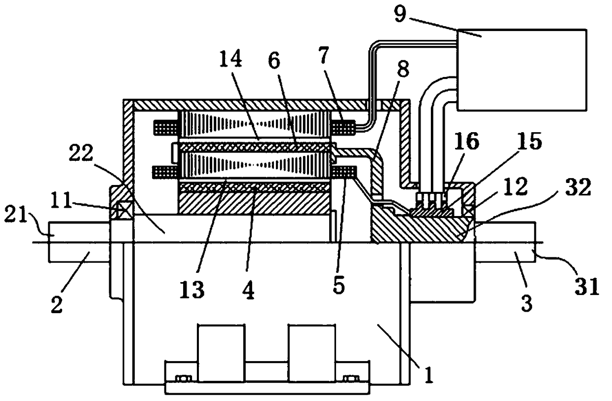
[0035] A magnetic coupling transmission device with constant power and speed regulation operation provided by the present invention will be further described in detail below in conjunction with the accompanying drawings.

[0036] seefigure 1 The first embodiment shown, wherein a magnetic coupling transmission device with constant power and speed regulation operation includes a machine base with a housing 1 fixedly arranged, and an input that is rotatably installed on the housing 1 through a first bearing 11 Shaft 2, and an output shaft 3 also rotatably mounted on said housing 1 via a second bearing 12. Wherein, the input shaft 2 has an input shaft connecting end 21 for connecting with a power device, and an input shaft internal part 22; the output shaft 3 has an output shaft connecting end 31 for connecting with a load, and the output shaft The inner part 32 of the machine; and the inner part 22 of the input shaft and the inner part 32 of the output shaft are arranged correspo...


PUM


Abstract

The invention provides a magnetic coupling transmission device running at constant power and adjustable speed. A second electromagnetic induction component is arranged on the shell of a frame and an input shaft or an output shaft. A converter device in a control mechanism receives electric energy from a first electromagnetic induction component arranged between the input shaft and the output shaft, modulates the electric energy and inputs the electric energy to the winding of the second electromagnetic induction component so as to enable the second electromagnetic induction component to produce electromagnetic torque assisting the input shaft or the output shaft in rotating. According to the magnetic coupling transmission device running at constant power and adjustable speed, slip power generated due to rotation speed difference between the input shaft and the output shaft can be collected fully and used to drive the input shaft or the output shaft to rotate, so that the input power from a drive device can be all converted into the output power of the output shaft under the condition of ignoring mechanical loss and stray loss, and the size of the output power of the output shaft is equivalent to the size of the input power of the drive device.

Description

technical field [0001] The invention relates to a magnetic coupling transmission device for constant power speed regulation operation, especially for constant power transmission, which can increase the transmitted torque when the output speed is low, and belongs to the field of mechanical transmission. Background technique [0002] From the perspective of transmission technology, the speed regulation operation of large rotating machinery comes from two requirements, one is the requirement of production technology, and the other is the requirement of energy saving. At present, the variable speed operation of large rotating machinery, the most representative practical applications are: frequency conversion speed regulation technology of three-phase asynchronous motor or permanent magnet motor, series pole speed regulation technology of wound rotor motor and speed regulation type hydraulic coupling transmission technology . In addition, for variable speed operation with a fixe...

Claims


Application Information

Patent Timeline
Patent Type & Authority Patents(China)
IPC IPC(8): H02K51/00
Inventor 漆复兴李宏涛
Owner JIANGSU MAGNET VALLEY TECH
Learn More