
Sectional steel concrete shear wall with replaceable wall toe component and wall toe component

A technology for concrete shear walls and shear walls, which is applied to building components, walls, and building structures. It can solve the problems that steel concrete shear walls are difficult to repair and cannot continue to be used, and achieve rapid recovery of earthquake resistance and easy installation. The effect of disassembly and flexible design

Active Publication Date: 2015-10-28
西安建筑科大工程技术有限公司
View PDF9 Cites 29 Cited by
  • Summary
  • Abstract
  • Description
  • Claims
  • Application Information

AI Technical Summary

Problems solved by technology

Therefore, the object of the present invention is to provide a steel concrete shear wall with a replaceable wall toe member and the wall toe member, so as to solve the problem that the steel concrete shear wall is difficult to repair after being damaged and cannot continue to be used

Method used


Image

  • Sectional steel concrete shear wall with replaceable wall toe component and wall toe component
  • Sectional steel concrete shear wall with replaceable wall toe component and wall toe component

Examples


Embodiment 1

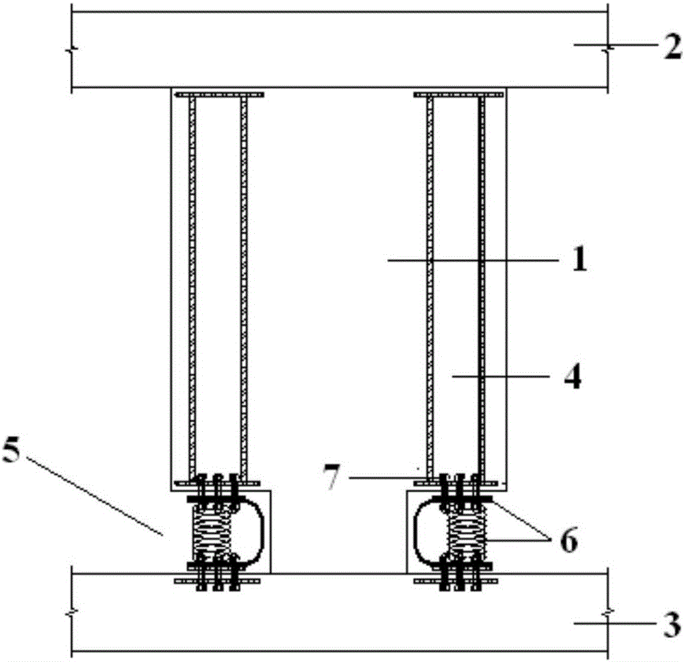
[0031] This embodiment provides a steel concrete shear wall with replaceable wall toe members, such as figure 1 and figure 2 As shown, it includes a shear wall 1, the top of the shear wall 1 is connected to the upper floor member 2, and the bottom of the shear wall 1 is connected to the lower floor member 3. The shear wall 1 has a built-in section steel 4, and the top of the section steel 4 is connected to the The upper floor member 2 is connected, and the bottom end of the section steel 4 is not connected to the lower floor member 3;

[0032] A wall toe placement cavity 5 is reserved on the shear wall 1 between the bottom end of the section steel 4 and the lower floor member 3, and a detachable wall toe member 6 is installed in the wall toe placement cavity 5, and the top of the wall toe member 6 It is connected with the bottom end of the section steel 4, and the bottom end of the wall toe member 6 is connected with the lower floor member 3;

[0033] The wall toe member 6 ...

Embodiment 2

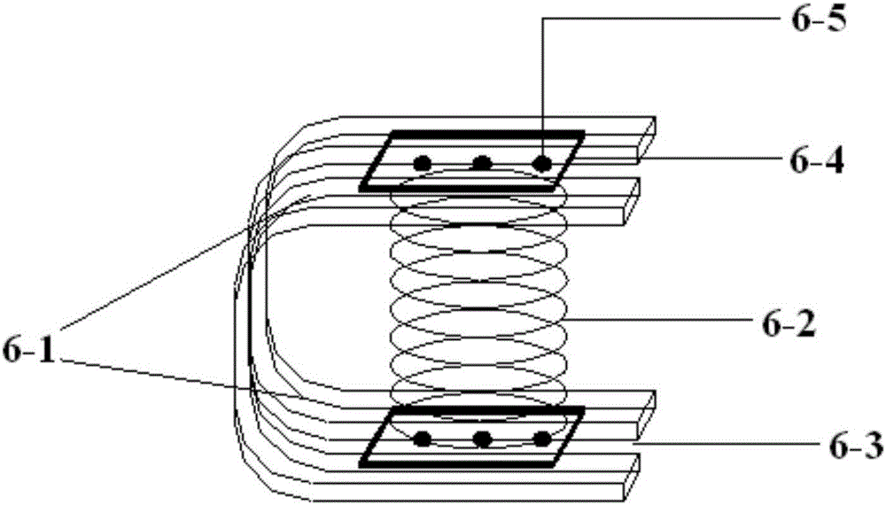
[0046] This embodiment provides a wall toe member, such as figure 2 As shown, it includes a U-shaped board 6-1 and an energy-dissipating spring 6-2, and the two sides of the U-shaped board 6-1 are symmetrically processed with through slots 6-3;

[0047] Both ends of the energy-dissipating spring 6-2 are equipped with a connecting steel plate 6-4, and the connecting steel plate 6-4 is stuck on the outside of the slot 6-3 so that the energy-dissipating spring 6-2 is installed inside the U-shaped board 6-1.

[0048]Further, both the U-shaped board 6-1 and the energy-dissipating spring 6-2 are made of steel with a low yield point.

[0049] Furthermore, the stiffness coefficient k of the energy dissipation spring 6-2 o =25×10 3 kN / m.


PUM

PropertyMeasurementUnit
Stiffness coefficientaaaaaaaaaa
Yield strengthaaaaaaaaaa
Yield pointaaaaaaaaaa

Abstract

The invention provides a sectional steel concrete shear wall with a replaceable wall toe component and the wall toe component. Sectional steel is built in the shear wall; a wall toe installing cavity is reserved on the shear wall arranged between the bottom end of the sectional steel and a lower story floor component; the dismountable wall toe component is arranged in the wall toe installing cavity; the top end of the wall toe component is connected with the bottom end of the sectional steel; the bottom end of the wall toe component is connected with the lower story floor component; the wall toe component comprises a U-shaped plate clamp and an energy dissipation spring; communicated clamp grooves are symmetrically processed in the two sides of the U-shaped plate clamp; connecting steel plates are arranged at the two ends of the energy dissipation spring; and the connecting steel plates are clamped on the outer side of the clamp grooves, so that the energy dissipation spring is arranged inside the U-shaped plate clamp. The sectional steel concrete shear wall and the wall toe component have the characteristics that a whole mother wall is enabled not to be damaged; the wall toe component can be replaced for many times; and the earthquake-proof function can be fast recovered.

Description

technical field [0001] The invention belongs to the field of construction engineering, and mainly relates to a steel concrete shear wall, in particular to a steel concrete shear wall with a replaceable wall toe member and the wall toe member. Background technique [0002] At present, the shear wall structure in the actual project is under the action of the earthquake, and the bottom area of ​​the shear wall is seriously damaged. Although the shear wall structure will not collapse as a whole, it is difficult to carry out post-earthquake repair work, which affects people's normal production and life. . [0003] The failure mode of the shear wall under the combined action of earthquakes is mainly bending failure and shear failure. Ordinary reinforced concrete shear walls are prone to shear failure, the concrete at the foot of the wall falls off, and the horizontal shear cracks at the bottom of the wall may penetrate. It cannot be repaired and cannot be used any longer, and can...

Claims


Application Information

Patent Timeline
IPC IPC(8): E04B2/58E04B2/60E04B1/98
Inventor 王威兰艳苏三庆高敬宇
Owner 西安建筑科大工程技术有限公司
Learn More