
An exhaust gas treatment device equipped with a limit sensor

Technology of an exhaust gas treatment device and sensor

Inactive Publication Date: 2017-02-08
XIAN UNIV OF SCI & TECH
View PDF5 Cites 0 Cited by
  • Summary
  • Abstract
  • Description
  • Claims
  • Application Information

AI Technical Summary

Problems solved by technology

However, in the long-term use process, due to the small distance between the adjacent connected sides of the rows of filter tubes, the conditions of exhaust gas filtration and adsorption are different from those of the open front and rear sides, which makes the filter tubes have different adsorption effects in the circumferential direction. distribution zone
At the same time, due to long-term work, this filter material has reached its service life due to the adsorption of a large amount of dirt, and the replacement of the filter material is complicated. In most cases, the entire filter device will be discarded and updated after the filter material life expires. device
resulting in waste

Method used


Image

  • An exhaust gas treatment device equipped with a limit sensor
  • An exhaust gas treatment device equipped with a limit sensor
  • An exhaust gas treatment device equipped with a limit sensor

Examples


Embodiment Construction

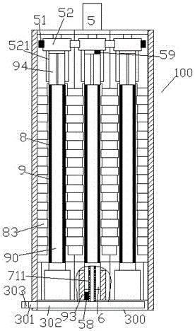
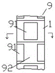
[0012] Combine below Figure 1-6 The present invention will be described in detail.

[0013] According to an embodiment, an exhaust gas treatment device 100 equipped with a limit sensor is used for treating exhaust gas of a processing equipment 200 with a plurality of internal workstations 201, wherein the processing equipment 200 includes six Each of the internal workstations 201 communicates with the annular gas gathering pipe 306 installed in the processing equipment 200 through the connecting pipe 202, and the annular gas gathering pipe 306 is provided with a The gas delivery pipe 301 connected to the waste gas treatment device 100 at the location, so that the processing waste gas generated in each of the internal workstations 201 is first transferred to the annular gas gathering pipe 306, and then transferred from the annular gas gathering pipe 306 to the waste gas treatment device 100 for filtering, the exhaust gas treatment device 100 includes a support frame, six exha...


PUM


Abstract

A waste gas treatment device (100) equipped with limiting sensors is used for conducting treatment on waste gas of processing equipment (200) provided with multiple internal workstations (201), wherein the processing equipment (200) comprises the six internal workstations (201) which are evenly arranged in the peripheral direction, each internal workstation (201) is communicated with an annular gas collection pipe (306) installed on the processing equipment (200) through a connecting pipe (202), and a gas delivery pipe (301) used for being communicated with the waste gas treatment device (100) which is located in the center of the processing equipment (200) is arranged on the annular gas collection pipe (306), so that processing waste gas produced in each internal workstation (201) is conveyed into the annular gas collection pipe (306) firstly and then conveyed into the waste gas treatment device (100) to be filtered from the annular gas collection pipe (306).

Description

technical field [0001] The present application relates to the field of exhaust gas treatment, in particular to an exhaust gas treatment device for treating exhaust gas of processing equipment with multiple internal working stations. Background technique [0002] In some processing equipment with multiple internal workstations, such as grinding processing equipment, it is often necessary to treat the exhaust gas with particles generated by the processing. In the exhaust gas treatment device, a plurality of adjacent filter tubes are often arranged to simultaneously filter the exhaust gas so as to increase the filtering area. However, in the long-term use process, due to the small distance between the adjacent connected sides of the rows of filter tubes, the conditions of exhaust gas filtration and adsorption are different from those of the open front and rear sides, which makes the filter tubes have different adsorption effects in the circumferential direction. distribution z...

Claims


Application Information

Patent Timeline
Patent Type & Authority Patents(China)
IPC IPC(8): B01D46/24B01D46/42
Inventor 庞绍芳解忧
Owner XIAN UNIV OF SCI & TECH
Learn More