
Sidetrack horizontal well track design method under control point constraint condition

A technology of sidetracking horizontal wells and constraints, applied in calculations, special data processing applications, instruments, etc., can solve problems such as inability to guarantee the optimal trajectory, inconvenient construction of the trajectory, and time-consuming and labor-intensive problems

Inactive Publication Date: 2014-04-02
CHINA UNIV OF PETROLEUM (EAST CHINA)
View PDF2 Cites 16 Cited by
  • Summary
  • Abstract
  • Description
  • Claims
  • Application Information

AI Technical Summary

Problems solved by technology

[0004] At present, the articles about the orbit design of anti-collision wellbore publicly published at home and abroad are relatively old, which are not suitable for the current design of anti-collision wellbore trajectory, and in the past design methods, when describing the obstacle position, complex coordinates are usually involved system projection and transformation; when solving to determine the coordinates of the obstacle position, it is necessary to solve complex equations to obtain the coordinates of the intersection point; when coupling the nodes after designing the horizontal projection diagram and the vertical section diagram, it is necessary to consider various node coupling situations, But the design process is more complicated
[0005] by formula It can be seen that when designing the track with the previous method, the curvature of the wellbore of the track often changes due to the change of the inclination angle, and the track designed in this way is not convenient for construction
[0006] The currently commonly used trajectory design software is the COMPASS directional well trajectory design software in the LANDMARK software series published by Halliburton. This software does not provide the design model of the wellbore trajectory. Therefore, when using this software for trajectory design, adjust the trajectory. Multiple trial calculations are required, which is time-consuming and laborious, and there is no guarantee that the final designed orbit is optimal

Method used


Image

  • Sidetrack horizontal well track design method under control point constraint condition
  • Sidetrack horizontal well track design method under control point constraint condition
  • Sidetrack horizontal well track design method under control point constraint condition

Examples


Embodiment Construction

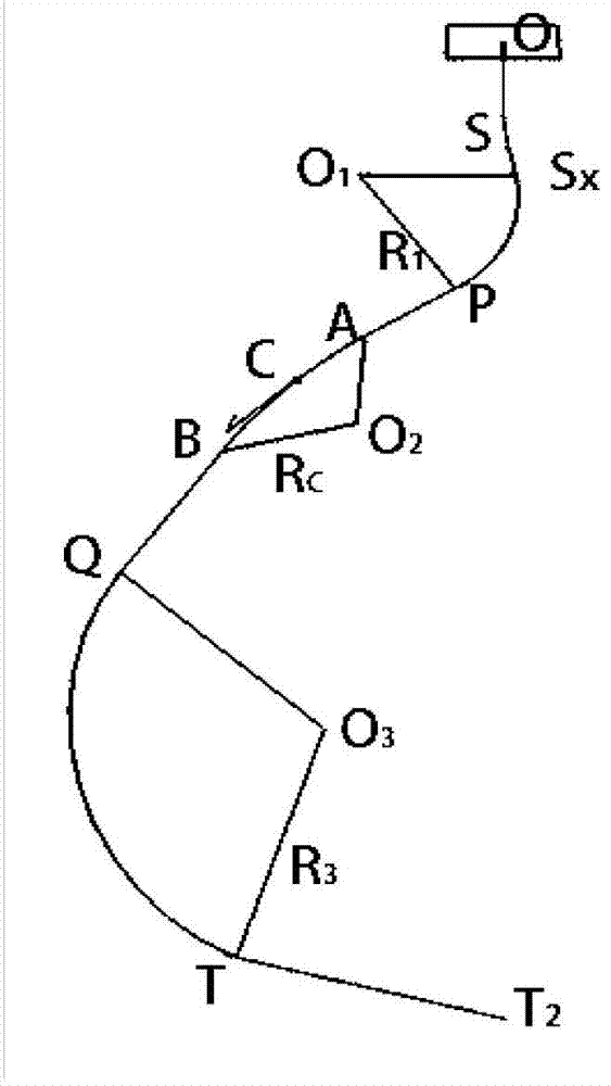
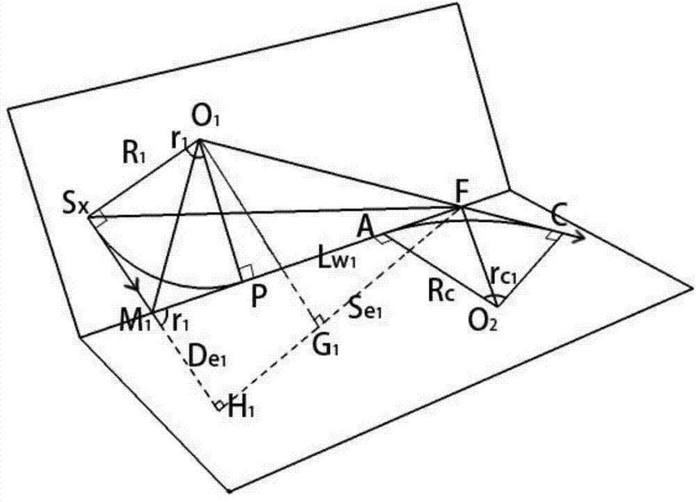
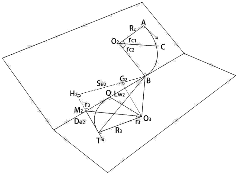
[0129] Such as figure 1 A section of the borehole track shown, S is the sidetracking point: the coordinates are (N S ,E S ,D S ), measured well depth L S ;Inclination angle α S ;Azimuth φ S . T is the first target point: coordinates (N T ,E T ,D T ); target well inclination angle α T ;target azimuth φ T . T2 is the second target point: coordinates (NT2 ,E T2 ,D T2 ); target well inclination angle α T2 ;target azimuth φ T2 . Anti-collision constraint point C: coordinates (N C ,E C ,D C ), between the sidetracking point S and the first target point T. Among them, the first target point T and the second target point T 2 There is a horizontal section in between, and the design of the drilling trajectory is relatively simple. This embodiment mainly studies the trajectory design model from the sidetracking point S to the first target point T. The target points in this embodiment all refer to the first target point.

[0130] The specific steps of the sidetracking...


PUM


Abstract

The invention discloses a sidetrack horizontal well track design method under control point constraint condition. The sidetrack horizontal well track design method comprises the following steps: determining known parameters; modeling well tracks; setting a hole deviation angle and an azimuth angle at a control point; solving the parameters of key points in a model; sieving a well track with the shortest total length. According to the sidetrack horizontal well track design method under control point constraint condition provided by the invention, the design models of the well tracks are given out, the hole deviation angle and the azimuth angle at the control point in the well tracks are selectively adopted, thus the well direction of the track at the control point is optimized, and then the method of the whole track is optimized; the design method is simple, tentative calculation is not required, the track with shorter length can be designed by inputting known conditions of design, so that the method is beneficial to shortening the drilling period and reducing the drilling cost.

Description

technical field [0001] The invention relates to the field of drilling engineering design, in particular to a sidetracking horizontal well track design method under the constraints of control points. Background technique [0002] At present, the domestic drilling industry is facing more and more infill wells and cluster wells, and the problem of anti-collision of well trajectory is becoming more and more prominent. How to realize anti-collision well trajectory design efficiently and with high quality is one of the main difficulties in the anti-collision problems of infill wells and cluster wells. [0003] When designing the anti-collision borehole trajectory, it is sometimes required that the borehole trajectory must pass through a certain control point before hitting the target, which increases the difficulty of the borehole trajectory design. [0004] At present, the articles about the orbit design of anti-collision wellbore publicly published at home and abroad are relati...

Claims


Application Information

Patent Timeline
IPC IPC(8): G06F17/50
Inventor 陈鹏举黄根炉李曹雄
Owner CHINA UNIV OF PETROLEUM (EAST CHINA)
Learn More