Low-partial-discharge-value single-structure-based mutual inductor and manufacturing method thereof

A transformer and low partial discharge technology, applied in the field of transformers, can solve the problems of uneven electric field distribution, high partial discharge value, waste of materials, etc. effect of value

Active Publication Date: 2015-10-21
HENAN SENYUAN ELECTRIC CO LTD
View PDF6 Cites 2 Cited by
  • Summary
  • Abstract
  • Description
  • Claims
  • Application Information

AI Technical Summary

Problems solved by technology

With the development of technology, many transformers can achieve lower partial discharge values, but there are still some problems with the partial discharge value of transformers with some structures. During the test, the partial discharge value is too high, which cannot meet the user's requirements, and sometimes it is even scrapped because it cannot meet the national standard, which not only wastes materials, but also makes the delivery date of the product unguaranteed.
[0003] The existing single-turn transformer structure, this structure only covers the primary winding of the transformer primary terminal (consisting of P1 terminal 3 and P2 terminal 7) and the conductive rod 4, and the P1 outgoing terminal 3 and P2 outgoing terminal 7 without any shielding or electric field treatment measures, under the action of high voltage, the electric field distribution of the primary winding will be uneven, especially between the two primary outlet terminals, the electric field will be greatly distorted with the sudden change of the medium, and at the same time There are also adverse conditions such as sharp points. When a voltage is applied to the primary terminal, various discharges such as inter-electrode discharge, creeping discharge, and tip discharge will occur near the primary terminal due to uneven electric field and distortion of the electric field.

Method used


Image

  • Low-partial-discharge-value single-structure-based mutual inductor and manufacturing method thereof
  • Low-partial-discharge-value single-structure-based mutual inductor and manufacturing method thereof
  • Low-partial-discharge-value single-structure-based mutual inductor and manufacturing method thereof

Examples


Embodiment Construction

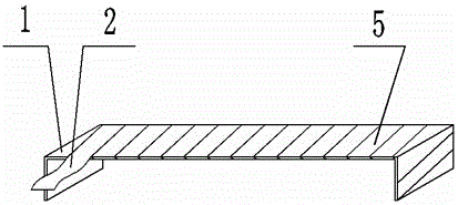
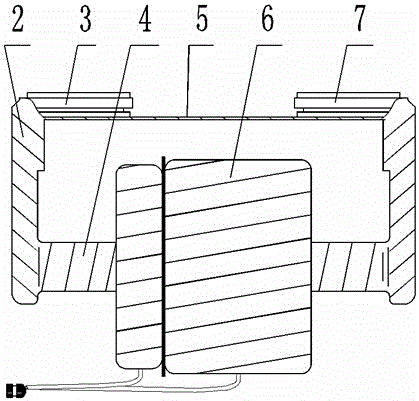
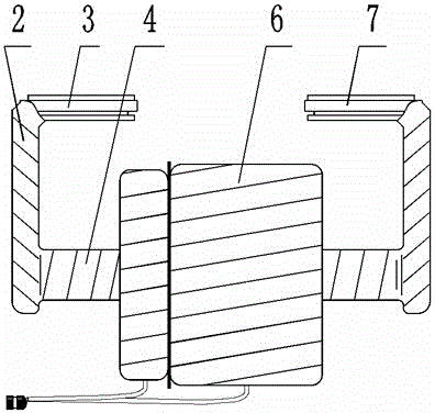
[0020] As shown in the attached figure, the single-turn structure transformer with low partial discharge value includes semiconductor crepe paper 2 , P1 terminal 3 , conductive rod 4 , transformer coil 6 , and P2 terminal 7 . C-shaped semiconductor cardboard 5 is arranged on the inner side of the pole 4 and the electric pole 4; the C-shaped semiconductor cardboard 5 is fixed on the conductive rod 4 through the semiconductor crepe paper 2; the transformer coil 6 is inserted into the primary winding of the transformer.

[0021] The primary terminal is composed of P1 outlet terminal 3 and P2 outlet terminal 7;

[0022] The C-shaped semiconductor paperboard 5 is formed by winding hard insulating paperboard 1 and semiconductor crepe paper 2, and the width of the hard insulating paperboard 1 is consistent with the width of the primary terminal;

[0023] The P1 terminal 3 and the P2 terminal 7 are welded to the conductive rod 4;

[0024] The transformer primary winding is composed o...


PUM


Abstract

The invention relates to a low-partial-discharge-value single-structure-based mutual inductor and a manufacturing method thereof. The low-partial-discharge-value single-structure-based mutual inductor comprises a piece of semiconductor crepe paper 2, a P1 terminal 3, a conducting rod 4, a mutual inductor coil 6, and a P2 terminal 7 and is characterized in that the conducting rod 4 is arranged below a primary terminal; a C-shaped semiconductor paper plate 5 is arranged at the inner side of the conducting rod 4 and is fixed on the conducting rod 4 by the semiconductor crepe paper 2; and the mutual inductor coil 6 is sleeved into a primary coil of the mutual inductor. The mutual inductor has the following advantages: the primary coil of the mutual inductor forms a uniform electric field under a high voltage and electric field intensities of all parts of the mutual inductor are distributed uniformly; the field intensity transition is in a smooth mode; no field intensity distortion phenomenon occurs; when the partial discharge value is measured in a test voltage state, the apparent discharge magnitude is low; and the partial discharge value inside the mutual inductor is reduced in a high voltage state.

Description

technical field [0001] The invention relates to a single-turn structure transformer with low partial discharge value and a manufacturing method thereof, belonging to the technical field of transformers. Background technique [0002] In the process of transformer production and use, the quality of partial discharge not only reflects the inherent quality of the transformer, but also involves the service life of the transformer, so the problem of partial discharge of the transformer has always been a concern of transformer manufacturers and users The problem. With the development of technology, many transformers can achieve lower partial discharge values, but there are still some problems with the partial discharge value of transformers with some structures. During the test, the partial discharge value is too high, which cannot meet the user's requirements, and sometimes it is even scrapped because it cannot meet the national standard, which not only wastes materials, but also...

Claims


Application Information

Patent Timeline
Patent Type & Authority Applications(China)
IPC IPC(8): H01F38/20H01F27/29H01F27/28H01F41/00
Inventor 陈耀刚娄军峰刘军超张伟
Owner HENAN SENYUAN ELECTRIC CO LTD
Why Eureka
Try Eureka