
Dedicated centrifugal tube and method for manufacturing cell blocks

A centrifuge tube and cell block technology, which is applied in the field of cytopathology, can solve the problems of the size and shape of the wax block, the inability to make a definite diagnosis of the patient, and the inability to make a cell block, so as to improve the positive rate of diagnosis and effectively It is beneficial to the quality control and standardized operation of cytopathology, and the effect of determining the location of cell distribution

Active Publication Date: 2015-10-21
昆明东环科技有限公司
View PDF5 Cites 5 Cited by
  • Summary
  • Abstract
  • Description
  • Claims
  • Application Information

AI Technical Summary

Problems solved by technology

However, these existing methods have different defects, the most obvious defect is: it is not suitable for the preparation of cell blocks when the number of cells or cell clusters is small, therefore, some clinical specimens cannot be made due to the small number of cells Cell-forming wax block, which cannot make a definite diagnosis for the patient; in addition, the position of the target cells (pathological cells) in the cell wax block is scattered and uncertain, and it is difficult to cut the diseased cells when slicing, or the distribution of cells on the slice is small , low density; the size and shape of the wax block are irregular, etc.

Method used


Image

  • Dedicated centrifugal tube and method for manufacturing cell blocks
  • Dedicated centrifugal tube and method for manufacturing cell blocks
  • Dedicated centrifugal tube and method for manufacturing cell blocks

Examples


Embodiment Construction

[0025] The present invention will be described in detail below in conjunction with examples and accompanying drawings, but the present invention is not limited thereto.

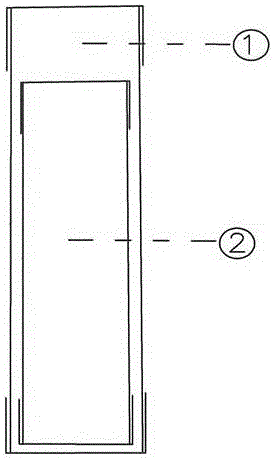
[0026] Such as figure 1 As shown, a special centrifuge tube for preparing cell blocks is composed of centrifuge tube ① and centrifuge tube caps ② and ③.

[0027] The centrifuge tube ① is open at both ends and is a cylindrical hollow tube with external threads on the outer surface of both ends (the external threads are not marked in the figure). Centrifuge tube caps ② and ③ are flat-bottomed, with a sealing ring (gasket) on the bottom of the cap (the sealing ring is not marked in the figure), and a closed type cap with internal threads on the surface of the inner wall (internal threads are not marked in the figure). The flat bottom is the structural basis for cells to be able to distribute on a flat surface. The centrifuge tube caps ② and ③ can be tightly engaged with the external threads at both ends of the...


PUM

PropertyMeasurementUnit
The inside diameter ofaaaaaaaaaa
Outer diameteraaaaaaaaaa
Lengthaaaaaaaaaa

Abstract

The invention discloses a dedicated centrifugal tube and method for manufacturing cell blocks. The dedicated centrifugal tube is composed of a cylindrical centrifugal pipe with two opened ends and two centrifugal tube covers. The surfaces of the pipe walls of two ends of the centrifugal tube are provided with external threads, the centrifugal tube covers are covers with a flat bottom, the bottoms of the covers are provided with a sealing ring (cushion), the internal walls are provided with internal threads, and the internal threads and the external threads can be engaged together to form a sealed cylindrical space. The cell block is produced by the following steps: heating a centrifugal tube containing matrix to liquidize the matrix, then adding cell (cluster) suspension on the upper surface of the matrix layer, turning the centrifugal tube upside down to mix the matrix and the cell suspension, then carrying out centrifugation, (or directly carrying out centrifugation), so as to enrich the cells to a plane on the bottom layer of the matrix through the matrix (cushion); after the matrix is cured, removing the centrifugal tube cover on the two ends of the centrifugal tube, pushing out the matrix containing a cell layer by a piston or pressurized air from the centrifugal tube, and cutting the matrix to manufacture cell blocks. The provided method can conveniently and efficiently make trace cell samples into a complete and regular cell block with a large cell distribution area and high cell density.

Description

technical field [0001] The invention belongs to the field of cytopathology, and in particular relates to a special centrifuge tube and a production method for producing cell blocks from specimens of cytopathology and surgical pathology. Background technique [0002] Cytopathology diagnoses many diseases and assesses health by analyzing cells or small clusters of cells. [0003] The most commonly used cytopathological technique is a pap smear. Cell smear is to smear cells or small cell groups on glass slides, stain with diagnostic reagents, and observe cell morphology under a microscope to diagnose various diseases or evaluate health status. The cell smear method has obvious limitations, mainly in: the cell smear cannot be replicated, once the cell smear is stained with a diagnostic reagent, it is difficult to perform additional staining and detection at the same time; it is difficult to perform immunohistochemistry and molecular pathology Blood, protein deposits, mucus int...

Claims


Application Information

Patent Timeline
IPC IPC(8): G01N1/28
Inventor 赵稳兴
Owner 昆明东环科技有限公司
Learn More