
Solid wire for gas-shielded arc welding, gas-shielded arc welding metal, welding joint, welding member, welding method, and method for manufacturing welding joint

A technology of arc welding and gas shielding, applied in arc welding equipment, welding equipment, manufacturing tools, etc., can solve the problems of corrosion resistance and aesthetic reduction of welded parts, and achieve good shape effect

Active Publication Date: 2015-10-14
NIPPON STEEL CORP
View PDF17 Cites 12 Cited by
  • Summary
  • Abstract
  • Description
  • Claims
  • Application Information

AI Technical Summary

Problems solved by technology

Such slag (oxide) has no conductivity, so the electrodeposition coating will not adhere to the slag on the surface of the welding bead to cause poor coating and coating defects, so there is corrosion resistance of the welded part after coating. Worry that sex and appearance decrease

Method used


Image

  • Solid wire for gas-shielded arc welding, gas-shielded arc welding metal, welding joint, welding member, welding method, and method for manufacturing welding joint
  • Solid wire for gas-shielded arc welding, gas-shielded arc welding metal, welding joint, welding member, welding method, and method for manufacturing welding joint
  • Solid wire for gas-shielded arc welding, gas-shielded arc welding metal, welding joint, welding member, welding method, and method for manufacturing welding joint

Examples


Embodiment 1

[0138] The manufacturing method of the solid welding wire for welding is as follows. That is, an ingot is produced by a vacuum melting method, forged, rolled, drawn, and annealed to form a welding wire raw material wire, and copper plating is further performed on the welding wire raw material wire, and then cold drawn to produce a solid wire with a diameter of 1.2 mm. welding wire. The chemical components (components of the entire welding wire including the plating layer) of the obtained solid welding wires are shown in welding wire Nos. 1 to 28 in Table 1. In addition, in Table 1, the chemical components of the content not included in the scope of the claims are underlined.

[0139] Using each welding wire having the chemical composition shown in the welding wire Nos. 1 to 28 in Table 1, steel sheets with a thickness of 2.3 mm (without zinc coating) having the chemical composition shown in the steel sheets No. 1 and No. 2 in Table 3 were used. Galvanized bare steel sheet) a...

Embodiment 2

[0224] As the solid welding wire for welding, the same welding wire as that used in the above-mentioned Example 1 was used, that is, the welding wire (welding wire No. Welding, to have the chemical composition shown in the steel plate No.1~12 of Table 3 (wherein, the composition of the steel sheet shown in Table 3 shows the composition of the parent steel sheet before galvanizing) plate thickness is 2.3mm zinc Clad steel plate for lap fillet welding. Welding conditions are also shown in Table 4 in the same manner as in Example 1. In addition, the zinc-plated steel sheet used for welding is such that the amount of the plating unit area weight on one side is 45 g / m 2 Those that have implemented hot-dip galvanizing on both sides by the way.

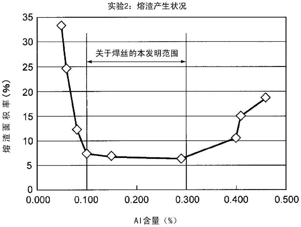
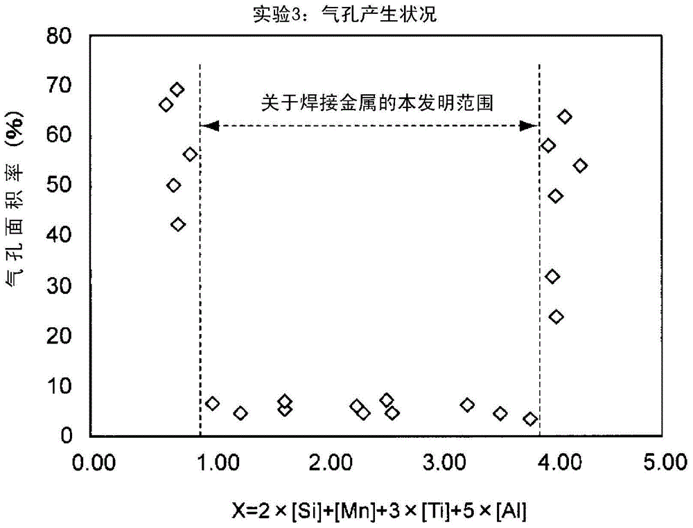
[0225] The composition of the weld metal in the welded joint obtained by the arc welding experiment on the above-mentioned zinc-coated steel sheet was analyzed, the results are shown in Table 5, and the generation of slag and the generatio...


PUM

PropertyMeasurementUnit
thicknessaaaaaaaaaa

Abstract

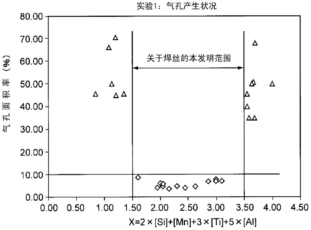
The present invention comprises a solid wire for gas-shielded arc welding which contains, by mass% relative to the total mass of the wire including plating, C: 0.03-0.15%, Si: 0.2-0.5%, Mn: 0.3-0.8%, P: 0.02% or less, S: 0.02% or less, Al: 0.1-0.3%, Ti: 0.001-0.2%, Cu: 0-0.5%, Cr: 0-2.5%, Nb: 0-1.0%, V: 0-1.0%. The remainder thereof comprises Fe and impurities, and value X of formula (I) is, by mass%, within the range of 1.5-3.5%. Furthermore, the present invention comprises a welding metal wherein value X of formula (I) is within the range of 1.0-4.0%. Furthermore, the present invention comprises a welding joint, a welding member, a welding method, and a method for manufacturing the welding joint which use the solid wire or the welding metal. Formula (I): X=2×[Si]+[Mn]+3×[Ti]+5×[Al]

Description

technical field [0001] The present invention relates to a solid welding wire for welding steel plates such as zinc-plated steel plates used for structural parts of automobile suspensions and the like by gas-shielded arc welding. In addition, the present invention relates to a weld metal (also referred to as weld metal, weld metal), welded joint, and welded part welded by a gas shielded arc welding method. Furthermore, the invention relates to a welding method based on the gas shielded arc welding method and to a welded joint. Background technique [0002] As is well known, zinc-plated steel sheets and zinc-alloy-plated steel sheets are often used as steel sheets for automotive suspension structural members that are painted after welding. In addition, gas-shielded arc welding typified by carbon dioxide gas-shielded arc welding is often used for welding structural parts of automobile suspensions. [0003] However, when the steel plate is arc-welded, pores may be generated in...

Claims


Application Information

Patent Timeline
Patent Type & Authority Applications(China)
IPC IPC(8): B23K35/30C22C38/00C22C38/14C22C38/50
CPCB23K35/3053B23K35/0255B23K35/0261B23K35/30B23K35/3073B23K35/308B23K35/3086C22C38/00C22C38/02C22C38/04C22C38/06C22C38/12C22C38/14C22C38/16C22C38/18C22C38/20C22C38/24C22C38/26C22C38/28C22C38/50C23C2/06C22C38/002B23K9/02
Inventor 钱谷佑儿玉真二土谷祥子内藤恭章
Owner NIPPON STEEL CORP
Learn More