Device for detecting image sensor performance and use method thereof
An image sensor and image detection technology, which is applied in image communication, television, electrical components, etc., can solve the problems of complex scenes, incapable of quantitative measurement, and not intuitive enough
- Summary
- Abstract
- Description
- Claims
- Application Information
AI Technical Summary
Problems solved by technology
Method used
Image
Examples
Embodiment 1
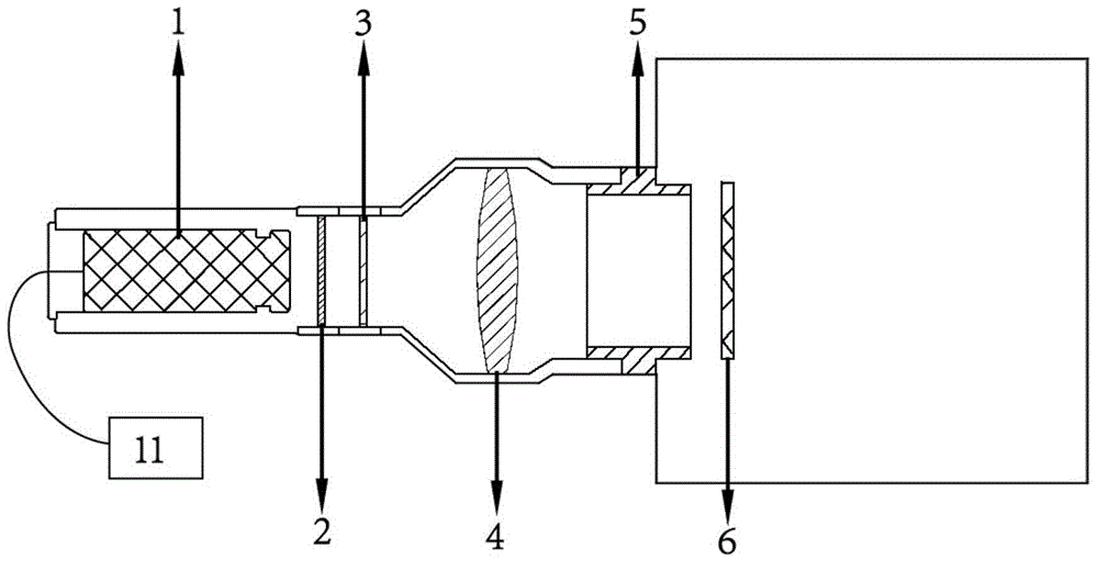
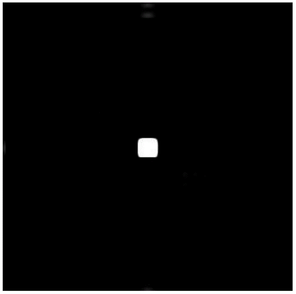
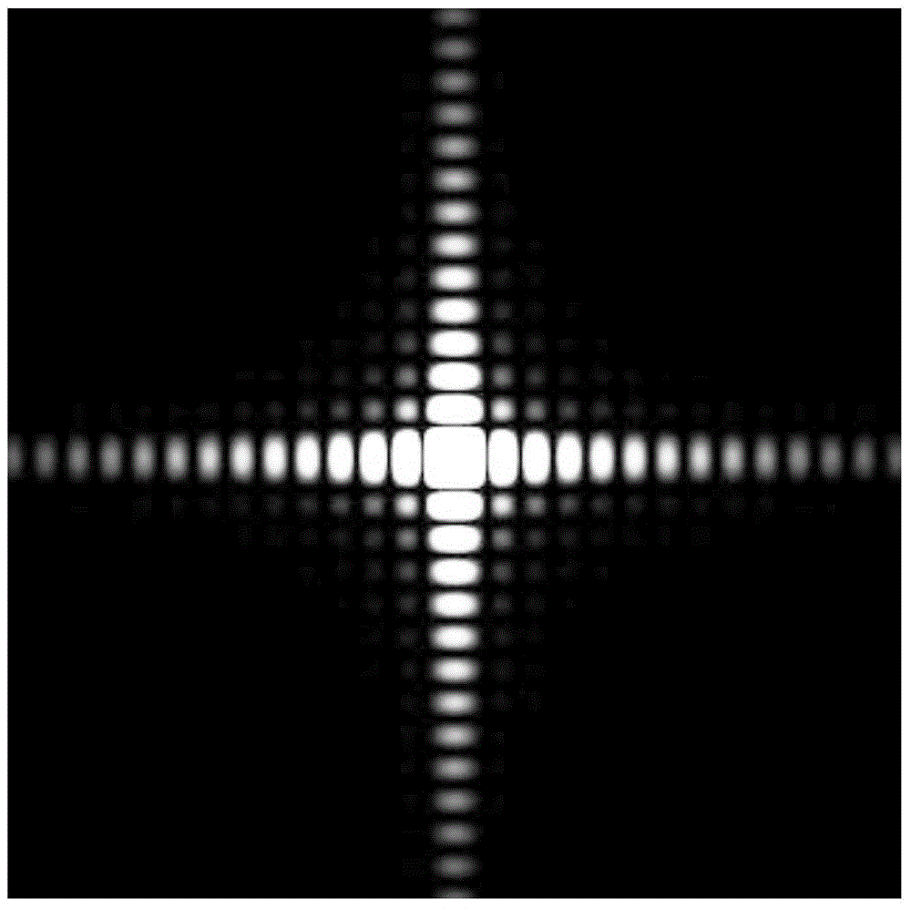
[0081] combine Figure 1-3 , a device for detecting the performance of an image sensor, comprising an adjustable optical attenuation sheet 2, a converging lens 4, a laser 1, a diffraction screen 3 and an adjustable ring 5, wherein the laser 1, the adjustable optical attenuation sheet 2, the diffraction The screen 3, the converging lens 4 and the adjustable ring 5 are sequentially fixed in the device, the right side of the adjustable ring 5 is provided with an image sensor 6, and the left end of the laser 1 is provided with a cable interface, and the power supply 11 is connected through a cable Electrically connected, so that the laser 1 emits monochromatic parallel light; by adjusting the power of the laser 1, the intensity of the parallel light emitted by the laser 1 can be adjusted, and accordingly, the light intensity of the diffraction pattern can be adjusted; by installing different attenuation ratios The adjustable light attenuating sheet 2 can also attenuate the intensi...
Embodiment 2
[0136] Such as figure 1 As shown, the present invention provides a device for detecting the performance of an image sensor and its use method. The structure and use method are the same as in Embodiment 1, wherein, firstly, the device is closely connected with the camera through the adjustable ring 5, and the The cable interface of the laser 1 is connected to the power supply 11 through a cable, and the laser 1 is turned on to emit monochromatic light. The monochromatic light passes through the adjustable light attenuation plate 2 to regulate the light intensity emitted by the laser 1, and the regulated parallel light reaches the Diffraction occurs on the diffraction screen 3, and the diffracted light beam is converged by the converging lens 4, passes through the adjustable ring 5, and reaches the surface of the calibration image sensor 6 or the image sensor 6 to be tested. Diffraction spots are clearly imaged.
[0137] In this embodiment, the diffraction screen 3 is selected ...
Embodiment 3
[0172] The parameter performance of camera three is measured on the device of the present invention, and its structure and usage method are the same as those in embodiment 1. The number of data bits of the image is 12 bits, and the maximum gray value that the image can achieve is 2 b -1=4095, according to the first case of calculating the full well capacity in embodiment 1, the gray value μ of a certain k-order diffraction spot y.k range of 0.891 (2 b -1)~0.909(2 b -1), calculated in this embodiment: 3648 ~ 3722, the gray value μ of the first-order diffraction spot of the diffraction image captured by the camera three is measured by software y·1 is 3648, within this range, so the calculation of the full well capacity is calculated using the first case, the background gray value μ y.dark is 150, the number of photons per one hundred square micrometers of the first-order diffraction spot per millisecond I 1 2252, the quantum effect η is 60%, and the single pixel area A is 10...
PUM
| Property | Measurement | Unit |
|---|---|---|
| Total length | aaaaa | aaaaa |
| Diameter | aaaaa | aaaaa |
Abstract
Description
Claims
Application Information
 - Generate Ideas
- Intellectual Property
- Life Sciences
- Materials
- Tech Scout
- Unparalleled Data Quality
- Higher Quality Content
- 60% Fewer Hallucinations
Browse by: Latest US Patents, China's latest patents, Technical Efficacy Thesaurus, Application Domain, Technology Topic, Popular Technical Reports.
© 2025 PatSnap. All rights reserved.Legal|Privacy policy|Modern Slavery Act Transparency Statement|Sitemap|About US| Contact US: help@patsnap.com


