
Load balancing mechanism

A load balancing and component technology, applied in mechanical equipment, desks with variable desktop heights, applications, etc., can solve the problems of large occupation space, large desktop space, occupation of desktop space, etc. Effect

Active Publication Date: 2015-10-14
HANGZHOU LIERKANG FURNITURE DESIGN CO LTD
View PDF6 Cites 2 Cited by
  • Summary
  • Abstract
  • Description
  • Claims
  • Application Information

AI Technical Summary

Problems solved by technology

The downside of the combination of cams and compression springs is that it takes up a lot of space, especially when this device is placed on a desk, taking up a lot of valuable desk space
Although the patent uses two cam combinations to try to reduce the desktop space occupied by the device, judging from the implementation of the patent by the patent applicant (WorkFit-S series products that have been listed), the occupied desktop space is still large

Method used


Image

  • Load balancing mechanism
  • Load balancing mechanism
  • Load balancing mechanism

Examples


Embodiment Construction

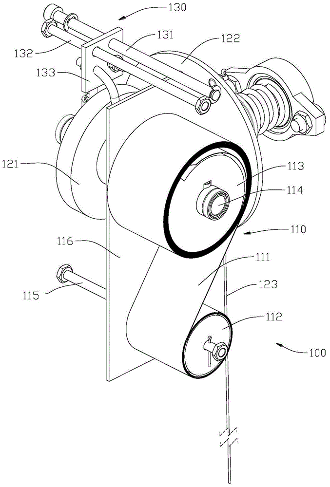
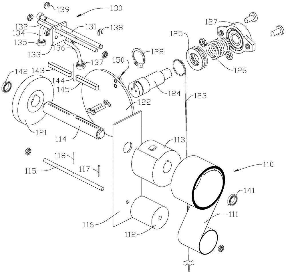
[0068] refer to Figure 1 to Figure 11 , The load balancing mechanism of the present invention can allow the user to move various loads within a certain stroke with little effort, and stop at the desired position. Loads include but are not limited to monitors, tablets, laptops, keyboards, mice, phones, graphics tablets, books, medical equipment, instruments, desktops, etc.

[0069] figure 1 It is a perspective view of the constant force output assembly 100 used in the embodiment of the present invention, figure 2 yes figure 1 exploded view. Wherein, in the constant torque spring assembly 110 , the head of the constant torque spring 111 hugs the storage wheel 112 by its own elastic force, and the tail of the constant torque spring 111 is fixed on the output wheel 113 . The shaft hole of the output wheel 113 is provided with a keyway, and is fixed on the keyway of the first shaft 114 through the interference fit of the first key 145 . The shaft hole of the adjusting roller...


PUM


Abstract

The invention discloses a load balancing mechanism which comprises a constant force output component, a lead screw component and a supporting component. The constant force output component can output constant torque and convert the constant torque into constant force. The lead screw component can adjust the output constant force according to the types of loads. The supporting component is used for supporting the constant force output component and the lead screw component. The constant force output component comprises a constant-torque spring outputting constant torque, a first shaft, an adjusting rolling wheel, a rotary disc, a second shaft and a first rope, the head of the constant-torque spring is wound on a storage wheel, and the tail of the constant-torque spring is fixed to an output wheel. The first shaft is in interference fit with the output wheel. The adjusting rolling wheel is in interference fit with the first shaft. The face of the rotary disc is closely attached to the face of the adjusting rolling wheel to generate friction force. The second shaft is fixedly arranged on the back face of the rotary disc and is concentric with the rotary disc. The first rope is used for converting the constant torque into the constant force. One end of the first rope is fixedly arranged on the rotary disc or the second shaft. When the second shaft rotates, the first rope is wound on or unwound from the second shaft, and the other end of the first rope is fixedly arranged on a mounting part of the supporting component.

Description

technical field [0001] The invention relates to a load balancing mechanism, which can provide a substantially constant force that does not change with displacement in the vertical direction or other directions, and the magnitude of the force can be adjusted. Background technique [0002] With the development of society, ergonomics has been paid more and more attention. Especially when human beings enter the information age, daily work and life are increasingly dependent on operating computers and other equipment. However, the relative position of many devices to the human body is not adjustable, and users of different sizes cannot use the devices in an ergonomically suggested manner. In addition, this non-adjustability forces the user to operate the device in the same posture for a long time, which can easily lead to health problems such as cervical spine and lumbar spine injuries. Studies have shown that changing your posture at regular intervals, such as alternating sitt...

Claims


Application Information

Patent Timeline
Patent Type & Authority Applications(China)
IPC IPC(8): F16F15/00F16H33/00A47B9/02
CPCA47B9/02F16F15/00F16H33/00
Inventor 向超
Owner HANGZHOU LIERKANG FURNITURE DESIGN CO LTD
Learn More