
Aeration pipe, aeration disc and immersion etching machine

An aeration tube and aeration disc technology, which is applied in the fields of aeration tubes, aeration discs and immersion etching machines, can solve the problems of weak airflow at the edge of the aeration disc, affecting the surface quality of the glass substrate, etc., and achieves high versatility. Effect

Active Publication Date: 2018-07-03
WUHAN CHINA STAR OPTOELECTRONICS TECH CO LTD
View PDF3 Cites 0 Cited by
  • Summary
  • Abstract
  • Description
  • Claims
  • Application Information

AI Technical Summary

Problems solved by technology

[0003] The invention provides an aeration tube, which solves the technical problem that the airflow at the edge of the aeration pan is weak and affects the surface quality of the glass substrate

Method used


Image

  • Aeration pipe, aeration disc and immersion etching machine
  • Aeration pipe, aeration disc and immersion etching machine
  • Aeration pipe, aeration disc and immersion etching machine

Examples


Embodiment Construction

[0021] The following will clearly and completely describe the technical solutions in the embodiments of the present invention with reference to the drawings in the embodiments of the present invention.

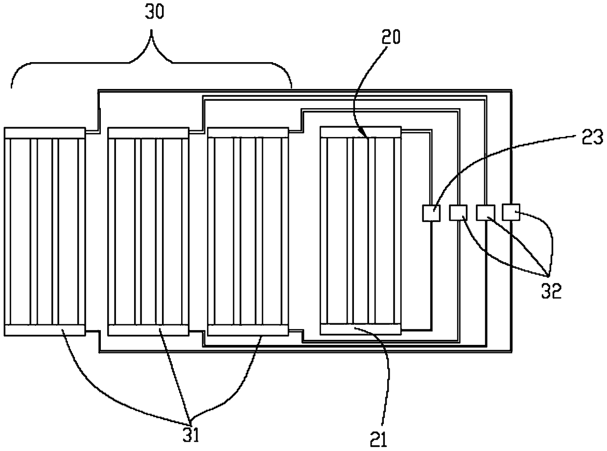
[0022] A preferred embodiment of the present invention provides an aeration tube and an aeration pan. The aeration pan is used to provide air pressure for the etching liquid when the immersion spray etching machine etches the glass substrate of the liquid crystal display.

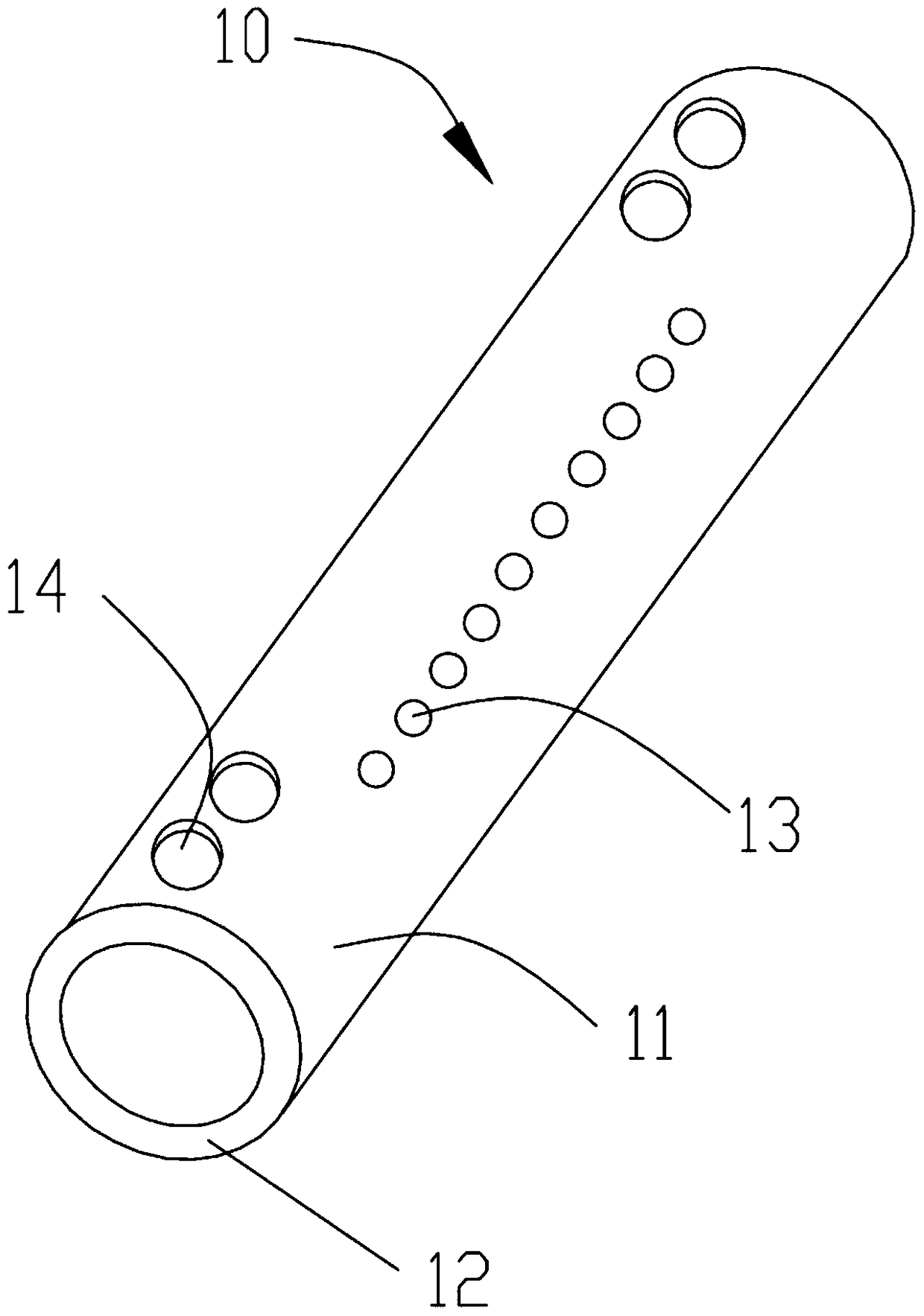
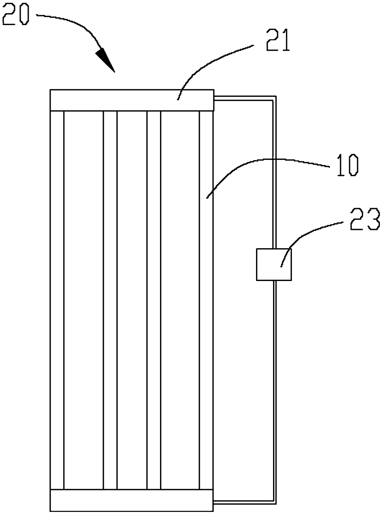
[0023] see figure 1 , the aeration tube 10 of the present invention is a hollow tube body, which includes a tube wall 11 , a cavity (not marked) surrounded by the tube wall 11 and open ends 12 located at both ends of the tube wall 11 . The pipe wall 11 is provided with several first air holes 13 arranged in a line along the axial direction. The plurality of linearly arranged first air holes 13 are at least arranged in one row. At least one second vent hole 14 is provided on the tube wall 11 near each ope...


PUM


Abstract

The invention provides an aeration tube, the aeration tube is a hollow tube body, which includes a tube wall, a cavity surrounded by the tube wall and open ends located at both ends of the tube wall, and the tube wall is along the axial direction There are several first ventilation holes arranged in a straight line, and a position is provided on the pipe wall close to each opening end and between the opening end and the outermost first ventilation hole among the several first ventilation holes. The second air hole, the straight line where the center of the second air hole is located is offset from the line where the center line of the first air hole is located, and the diameter of the first air hole is smaller than the diameter of the second air hole. The invention also provides an aeration pan and an immersion etching machine.

Description

technical field [0001] The invention relates to the technical field of liquid crystal panel manufacturing, in particular to an aeration tube, an aeration disc and an immersion etching machine. Background technique [0002] Liquid crystal display is the mainstream flat panel display device technology in the market today. The general structure of the liquid crystal glass substrate of the existing liquid crystal display includes: a TFT substrate and a CF substrate laminated up and down, and liquid crystal molecules poured between the TFT substrate and the CF substrate . Before the standard liquid crystal glass substrate is formed, it is necessary to thin, cut and separate the glass substrate mounted on the plate. Wherein, thinning refers to reducing the glass thickness of the two opposite outer surfaces of the glass substrate to meet the required thickness of the liquid crystal glass substrate as specified in the design. In the prior art, commonly used thinning equipment incl...

Claims


Application Information

Patent Timeline
Patent Type & Authority Patents(China)
IPC IPC(8): C03C15/00
Inventor 刘亮尹德胜
Owner WUHAN CHINA STAR OPTOELECTRONICS TECH CO LTD
Learn More