
Nanometer bead milling system and nanocrystalline microsphere preparation method

A technology of nanocrystalline microspheres and nanobeads, which is applied in the direction of grain processing, etc., can solve the problems of unreasonable design of the grinding chamber, affecting the dispersion effect of the powder pulverizer, continuous output, etc., and achieves controllable and improved quality indicators. Apparent surface area, effect of increasing product yield

Active Publication Date: 2015-10-14
GUANGXI NON FERROUS METALS GROUP HUIYUANMENGYE
View PDF5 Cites 2 Cited by
  • Summary
  • Abstract
  • Description
  • Claims
  • Application Information

AI Technical Summary

Problems solved by technology

Due to the unreasonable design of the grinding chamber, the grinding media (beads) are irregularly gathered at the slurry outlet of the grinding chamber, which cannot give full play to the full performance of the microbeads and affects the dispersion effect of the powder pulverizer.
[0004] The bead mills in the prior art all have a precise screen, its function is to make the slurry flow out from the screen, and the grinding bead particles are blocked by the screen and continue to work in the cavity, but the bead mill has no effect on the screen. There are requirements for the gap of the mesh, and the gap must not be larger than half of the average diameter of the grinding medium (beads). Due to the advancement of technology, the particle size of the grinding medium is getting smaller and smaller. There are already 0.015mm beads, and the screen is uniform. The gap is only 0.007mm, which is very difficult to manufacture and difficult to use and maintain. If finer beads continue to appear, the screen structure will not be realized
As of today, the above deficiencies have not been resolved
[0005] In addition, the bead mills of the prior art are all single-trough (barrel) circular grinding during grinding, and cannot continuously feed materials and output continuously. Only one groove (barrel) that passes the grinding can be discharged to the next barrel (trough). ) milling, the output is low, and the particle size distribution of the abrasive is wide

Method used


Image

  • Nanometer bead milling system and nanocrystalline microsphere preparation method
  • Nanometer bead milling system and nanocrystalline microsphere preparation method

Examples


Embodiment Construction

[0027] The present invention will be further described below in conjunction with the accompanying drawings and embodiments.

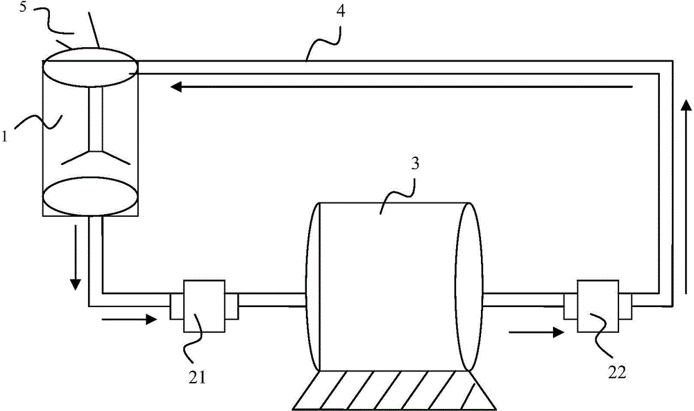
[0028] figure 1 It is a schematic diagram of the structure of the nano-bead milling system of the present invention.

[0029] See figure 1 , the nano bead milling system provided by the present invention comprises a stirring tank 1, a bead mill 3, a first pump 21 and a second pump 22, the outlet of the stirring tank 1 is connected to the inlet of the first pump 21 through a pipeline 4, and the first The outlet of the pump 21 is connected to the inlet of the bead mill 3 through a pipeline, the outlet 38 of the bead mill is connected to the inlet of the second pump 22 through the pipeline 4, and the outlet of the second pump 22 is connected to the inlet of the stirring tank 1 through the pipeline 4 connected.

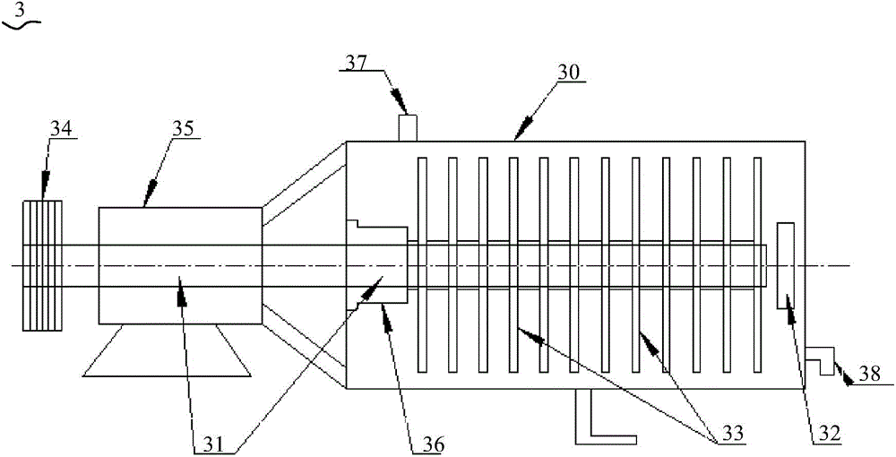
[0030] figure 2 It is a schematic structural diagram of the nano bead mill in the embodiment of the present invention.

[0031] See figure...


PUM


Abstract

The invention discloses a nanometer bead milling system and a nanocrystalline microsphere preparation method. The nanometer bead milling system comprises a stirring tank, a bead mill, a first pump and a second pump. An outlet of the stirring tank is connected with an inlet of the first pump through a pipe. An outlet of the first pump is connected with an inlet of the bead mill through a pipe. An outlet of the bead mill is connected with an inlet of the second pump through a pipe. An outlet of the second pump is connected with an inlet of the stirring tank through a pipe. The nanometer bead mill is not provided with a screen mesh. The technical problems that the particle size of powder bodies milled through an existing bead milling system cannot reach the nano-scale size, continuous charge production cannot be realized, and the output is low are solved.

Description

technical field [0001] The invention belongs to the field of nano-powder grinding and dispersing, and in particular relates to a nano-bead milling system and a preparation method of nano-crystalline microspheres. Background technique [0002] Nanotechnology is an important technical field in the development of science and technology today. Nanotechnology will create another wave of technological innovation and industrial revolution, and its application fields are very extensive, covering the electronics industry, optoelectronics industry, medical biochemical industry and basic industries. Regardless of the field of application, nanoscale materials are required. How to obtain nano-scale powder has become a joint research topic among production, learning and research. [0003] In the past ten years, although there have been several bead mills capable of preparing nano-scale powders, such as disc-type bead mills and pin-type bead mills, they all have shortcomings. Due to the...

Claims


Application Information

Patent Timeline
Patent Type & Authority Applications(China)
IPC IPC(8): B02C17/16B02C17/18
CPCB02C17/10B02C17/16B02C17/183B02C17/24
Inventor 万维华陈奇志韦国柱方皓王绍立陆宾莫秀恒梁鸿雁吴炼卢彥越贾艳桦卢碧翠韦革斌曾德超周维
Owner GUANGXI NON FERROUS METALS GROUP HUIYUANMENGYE
Learn More