
Plasma waste gas treatment equipment and treatment process

A technology of waste gas treatment and plasma, which is applied in the direction of separation method, dispersed particle separation, chemical instruments and methods, etc., can solve the problems that are easy to cause danger and affect the discharge effect, and achieve the effect of avoiding secondary pollution

Active Publication Date: 2015-10-14
南通联航环保科技有限公司
View PDF5 Cites 2 Cited by
  • Summary
  • Abstract
  • Description
  • Claims
  • Application Information

AI Technical Summary

Problems solved by technology

[0004] Plasma generators in the prior art use several positive plates corresponding to several negative plates to generate discharge, or positive rods correspond to cylindrical negative plates. When connecting high-voltage positive and negative electrodes, several positive and negative electrodes need to be connected with high-voltage positive and negative If there is a false or missing connection, it will not only affect the discharge effect, but also easily cause danger.

Method used


Image

  • Plasma waste gas treatment equipment and treatment process
  • Plasma waste gas treatment equipment and treatment process

Examples


Embodiment 1

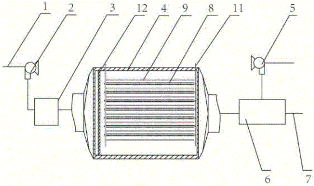
[0037] The components of the plasma exhaust gas treatment equipment are connected, the exhaust gas enters from the air inlet pipe, and is introduced into the dust filter through the induced draft fan. The filtered exhaust gas enters the plasma processor, and after the decomposition and purification of the plasma, it is discharged into the ozone processor. The air blower blows into the ozone processor and mixes with the purified gas. The temperature of the ozone processor is 60°C. The ozone generated by the plasma processor is removed and discharged through the exhaust pipe. The exhaust gas concentration is 1g / m3 and the exhaust gas flow rate is 150L. / min, the exhaust gas removal rate after the final purification is 98%.

Embodiment 2

[0039] The components of the plasma exhaust gas treatment equipment are connected, the exhaust gas enters from the air inlet pipe, and is introduced into the dust filter through the induced draft fan. The filtered exhaust gas enters the plasma processor, and after the decomposition and purification of the plasma, it is discharged into the ozone processor. The air blower blows into the ozone processor and mixes with the purified gas. The temperature of the ozone processor is 60°C. The ozone generated by the plasma processor is removed and discharged through the exhaust pipe. The concentration of the exhaust gas is 2g / m3 and the flow rate of the exhaust gas is 150L. / min, the exhaust gas removal rate after the final purification is 97%.


PUM


Abstract

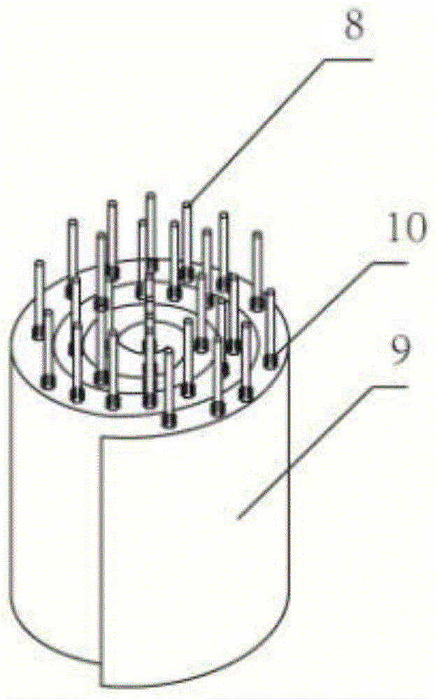
The invention relates to a plasma waste gas treatment system which is characterized by comprising an air inlet pipeline, an induced draft fan, a dust filter, a plasma processor, an air blower, an ozone processor and an exhaust duct, wherein the plasma processor comprises a plurality of metal bars and steel plates which are arranged in parallel, the setting direction of the metal bars and the steel plates is consistent with the direction of air flow, a plurality of sharp ends are arranged around the metal bars, the metal bars are arranged in spiral curly layers of the steel plates, and one ends of the metal bars are fixed on a stainless steel framework. A waste gas treatment process comprises the following steps: dust filtering, plasma treatment, ozone treatment and purification and discharge. The plasma waste gas treatment system and the waste gas treatment process have the benefits that the integrated steel plates are connected with high-voltage negative electrodes, so that the phenomenon of virtual connection or connection leakage caused by connection of a plurality of steel plates and high-voltage negative electrodes in the prior art can be effectively avoided; the ozone processor is additionally arranged behind the plasma processor, so that excessive ozone generated by the plasma processor is subjected to reduction treatment, and secondary pollution is avoided.

Description

technical field [0001] The invention relates to the field of waste gas treatment, in particular to the field of plasma waste gas treatment, in particular to plasma waste gas treatment equipment and a treatment process. Background technique [0002] Environmental pollution caused by industrial waste gas is one of the important sources of environmental pollution. A large amount of organic and inorganic substances harmful to human body in industrial waste gas are directly discharged into the atmosphere, which will cause serious harm to the environment and human body. With the continuous improvement of the degree of industrial socialization, people's awareness of environmental protection is also increasing, and energy conservation and emission reduction has become an area of ​​focus. In the process of exhaust gas purification, traditional methods usually use spray absorption, catalytic combustion, activated carbon adsorption, etc. Although several methods can absorb or decompos...

Claims


Application Information

Patent Timeline
IPC IPC(8): B01D53/32B01D46/00
Inventor 孙浩
Owner 南通联航环保科技有限公司
Learn More