
Taper double control automatic vacuum lead smelting furnace

A lead melting furnace, automatic technology, applied in the direction of furnace, furnace type, lighting and heating equipment, etc., can solve the problems of increased raw material occupation, large energy consumption, poor thermal insulation performance of the furnace body, etc., to prevent occupational hazards and environmental pollution Effect

Inactive Publication Date: 2015-09-30
ANHUI UNIV OF SCI & TECH
View PDF8 Cites 4 Cited by
  • Summary
  • Abstract
  • Description
  • Claims
  • Application Information

AI Technical Summary

Problems solved by technology

[0003] 1) Excessive energy consumption;
[0004] 2) The lead fume produced during the melting process (lead fume and lead dust is colorless and odorless, exists in the atmosphere in an aerosol state, is a respirable dust, and is extremely harmful to the human body), and is directly discharged into the atmosphere, which may easily cause employees to "lead" poisoning and environmental pollution
[0005] 3) The melting speed of lead is much higher than the oxidation speed of red lead, which is an oxidized product of lead grains. Due to the poor thermal insulation performance of the furnace body, relying on constant temperature control, there is unnecessary heating work and a waste of energy
[0006] 4) Since the shape of the furnace body is round or cylindrical, a certain amount of lead needs to be melted in advance as the base (commonly known as the bottom of the pot or soup), so it not only increases the occupancy of raw materials, but also continues to heat in order to maintain a constant temperature, wasting energy
[0007] 5) The furnace body of the traditional lead melting furnace is welded by high-temperature-resistant materials alone, and the thermal insulation performance is poor. In order to meet the production needs and maintain high temperature, only the electric heating is continuously activated to maintain a constant temperature, which greatly wastes energy.

Method used


Image

  • Taper double control automatic vacuum lead smelting furnace

Examples


Embodiment Construction

[0019] In order to make the technical means, creative features, goals and effects achieved by the present invention easy to understand, the present invention will be further described below in conjunction with specific illustrations.

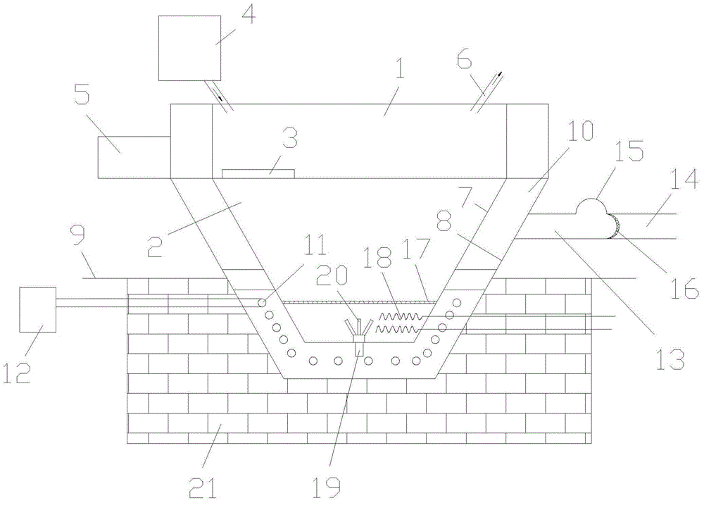
[0020] like figure 1 As shown, a conical dual-control automatic vacuum lead-melting furnace includes a furnace body, which is divided into a preheating chamber 1 at the upper part and a melting chamber 2 located at the lower part of the preheating chamber 1. The shape of the preheating chamber 1 is a cylinder Its bottom is used as the top cover of the melting chamber 2 to absorb the waste heat of the melting chamber 2. A 0.6*2cm groove is left around the bottom of the preheating chamber 1, and a lead drop port 3 is provided (closed in the preheating state) ; The side of the preheating chamber 1 is connected with an oxidation furnace waste heat collection device 4 (this device is a patent ZL201020609800.0 of the company), which absorbs the waste ...


PUM


Abstract

The invention discloses a taper double control automatic vacuum lead smelting furnace. The taper double control vacuum lead smelting furnace integrates a preheating cabin with a melting cabin, the solar heating and the electric heating are automatically switched, and the taper vacuum lead smelting furnace fully uses waste heat. In the production process, not only can the solar thermal energy be effectively used, but also the heat energy generated in the production process is also fully recycled, and the energy-saving goal is achieved; the lead fume generated in the lead melting furnace is collected in an airtight mode and passes through an oxidizing furnace, then the original lead smoke and the lead smoke generated by the oxidizing furnace are discharged to a tail gas purifying system in an airtight mode, and the occupational hazard and the environmental pollution are fundamentally prevented from occurring effectively.

Description

technical field [0001] The invention relates to the technical field of smelting equipment, in particular to a conical double-control automatic vacuum lead melting furnace. Background technique [0002] At present, at home and abroad, the first process of dry production of yellow lead and red lead is to melt lead ingots into lead water through a lead melting furnace at high temperature. A yellow lead and red lead dry process production line (25 tons of yellow lead or red lead per day) needs to be equipped with 3-4 lead melting furnaces, and each lead melting furnace is equipped with three sets of 5KW electric heating wires, so the monthly single melting The power consumption of the lead furnace is as high as 43,000 kwh (excluding the power consumption of the motor), which is a high energy consumption equipment. The traditional lead-melting furnaces used in the industrial production of red lead and yellow lead products are all semi-closed cuboids or cylinders with a "lead (wa...

Claims


Application Information

Patent Timeline
Patent Type & Authority Applications(China)
IPC IPC(8): F27B19/04
Inventor 朱可可
Owner ANHUI UNIV OF SCI & TECH
Learn More