
Rotary main shaft device for micro electric spark machining machine

A technology of rotating spindle and spark machining, applied in electric machining equipment, accessories, metal machining equipment, etc., can solve the problems of complex and tiny device machining technology, and achieve the effect of improving machining quality, reducing production cost and improving production efficiency

Inactive Publication Date: 2015-09-30
SHENYANG LIGONG UNIV
View PDF9 Cites 5 Cited by
  • Summary
  • Abstract
  • Description
  • Claims
  • Application Information

AI Technical Summary

Problems solved by technology

[0012] The purpose of the present invention is to provide a rotating spindle device of a micro electric discharge machining machine, which adopts advanced micro discharge electric discharge machining technology, solves the problems of piezoelectric ceramic macro and micro drive, micro electrode clamping, high-speed rotation, automatic wire feeding technology and micro Hole EDM technology and other key technical problems, the development of micro-EDM CNC system, to solve the processing problems of high-precision micro-parts; in the development of micro-non-traditional processing equipment, to solve the problem of complex micro-device processing technology, through the research of this project and breakthroughs in key technologies to form serialized products and equipment to enhance technological progress in aerospace, medical equipment, bioengineering, information, semiconductor industry, automobiles and other related industries

Method used


Image

  • Rotary main shaft device for micro electric spark machining machine
  • Rotary main shaft device for micro electric spark machining machine

Examples


Embodiment Construction

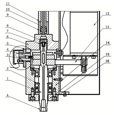
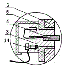
[0021] Referring to the accompanying drawings, a rotating spindle device of a micro electric discharge machine includes a rotating spindle 1, a precision bearing 2, an electrical device 3, a brush 4, an insulating plastic 5, an upper end cover 6, a first insulator 7, and a ceramic material 8 , the second insulator 9, the insulating inner tube 10, the outer casing of the liquid pipe 11, the motor 12, the timing belt 13, the main shaft casing 14, the lower end cover 15, the bolt 16, the motor 12 is installed on the bracket of the main shaft casing 14, and the timing belt 13 is one end Set on the output shaft of the motor 12, the other end is set on the pulley of the rotating main shaft 1, the second insulator 9 is installed on the upper end cover 6, the insulating inner tube 10 is installed in the second insulator 9, and the upper part of the second insulator 9 and the The outside of the insulating inner pipe 10 is installed with a liquid pipe outer casing 11, and the first insul...


PUM


Abstract

The invention provides a rotary main shaft device for a micro electric spark machining machine which is applied to the technical field of micro machine manufacturing of micro machining limitation. The rotary main shaft device for the micro electric spark machining machine comprises a rotary main shaft, precision bearings, an electrifying device, an electric brush, insulating plastic, an upper end cover, a first insulating body, a ceramic material, a second insulating body, an inner insulating pipe, an outer liquid passing pipe sleeve, a motor, a synchronous belt, a main shaft shell, a lower end cover and bolts. The motor is arranged on a stand of the main shaft shell. One end of the synchronous belt is connected with an output shaft of the motor in a sleeved mode, and the other end is connected with a belt pulley of the rotary main shaft in a sleeved mode. The second insulating body is arranged on the upper end cover. The inner insulating pipe is arranged inside the second insulating body. The outer liquid passing pipe sleeve is arranged on the upper portion of the second insulating body and the external of the inner insulating pipe. A micro hole, a groove and a curved face with the diameters lower than 0.1 mm can be machined on quenched steel hard alloy, stainless steel and other super-hard and super-soft conductive materials, a high-frequency supersonic vibration technology is adopted by the rotary main shaft, the production efficiency is improved, the production cost and the electrode loss are lowered, and the machining quality is improved.

Description

technical field [0001] The invention relates to a rotating spindle device of a micro-electric discharge machining machine in the technical field of micro-machining limit micro-machining. Background technique [0002] At present, modern manufacturing technology is one of the important means for a country to develop its economy, and it is also an important basis for measuring the level of a country's industry. From the current point of view, the development of modern manufacturing technology mainly presents two trends: one is the computer integrated manufacturing technology that pursues the automation of the manufacturing system; the other is the micro-mechanical manufacturing technology that seeks the limit of the micro-processing of the manufacturing system. [0003] Microfabrication technology originated from planar silicon technology. With the development and demand of semiconductor devices, integrated circuits, micromachines and other technologies, microfabrication techno...

Claims


Application Information

Patent Timeline
IPC IPC(8): B23H1/00
CPCB23H1/00B23H11/00
Inventor 张辽远
Owner SHENYANG LIGONG UNIV
Learn More