
Worm grinding wheel gear grinding surface distortion compensation method

A technology of worm grinding wheel and compensation method, which is applied in the direction of gear teeth, worms, gear teeth manufacturing devices, etc., and can solve the problem of high requirements for machine tools

Active Publication Date: 2015-09-30
CHONGQING UNIV
View PDF5 Cites 18 Cited by
  • Summary
  • Abstract
  • Description
  • Claims
  • Application Information

AI Technical Summary

Problems solved by technology

Guo Erkuo et al. established a mathematical model for the modification error of the profile grinding tooth, and proposed a method of adjusting the installation angle of the grinding wheel to optimize the contact line to improve the tooth surface distortion, but this method is not suitable for worm grinding wheel grinding; Tran VT. et al. A method of adding an additional rotation angle of the gear to reduce the tooth distortion is proposed when grinding drum-shaped teeth. Although the effect is good, the requirements for the machine tool are extremely high

Method used

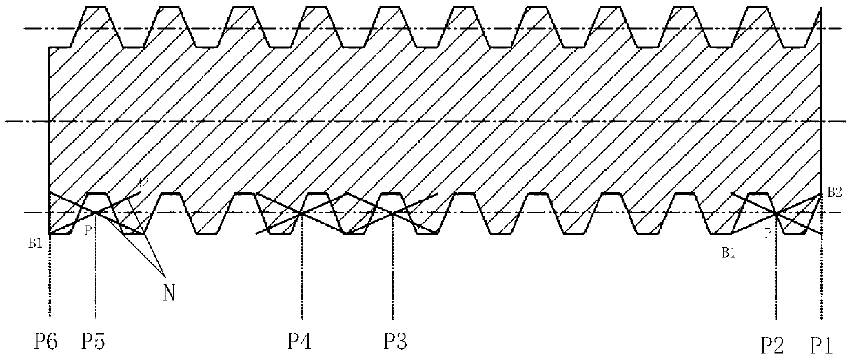
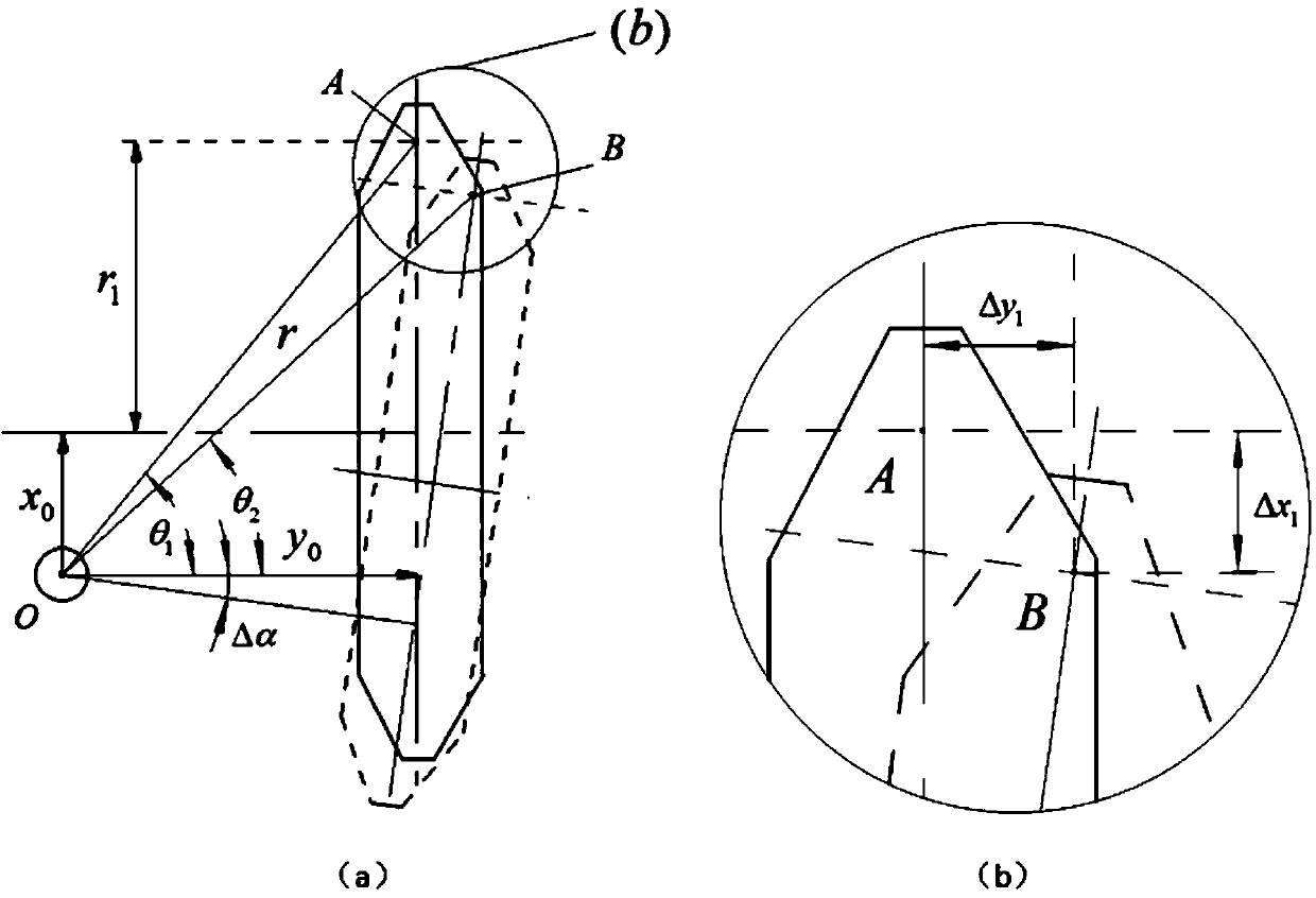

Image

  • Worm grinding wheel gear grinding surface distortion compensation method
  • Worm grinding wheel gear grinding surface distortion compensation method
  • Worm grinding wheel gear grinding surface distortion compensation method

Examples


Embodiment Construction

[0046] The present invention will be described in further detail below in conjunction with the accompanying drawings and specific embodiments.

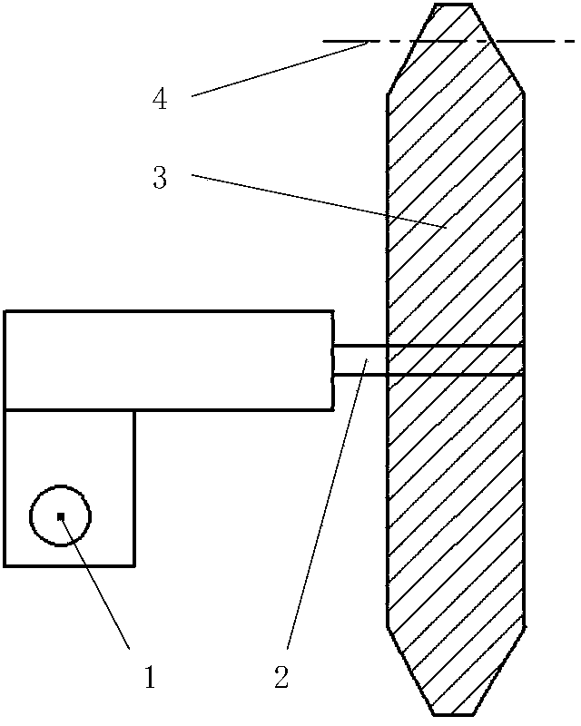
[0047] According to the present invention, the diamond roller wheel used to dress the worm grinding wheel should include two movements of rotation and deflection according to the requirements, and the position of the rotation axis of the roller should be at the front end of the deflection axis. Its specific structure is as follows: figure 1 shown. In the figure, 1 represents the deflection axis of the roller, 2 represents the rotation axis of the roller, 3 represents the diamond roller, and 4 represents the pitch line of the roller.

[0048] The grinding process of worm grinding wheel is generally divided into rough grinding and fine grinding, and the grinding allowance of rough grinding is greater than that of fine grinding. Therefore, the worm grinding wheel is divided into rough grinding area, fine grinding area and intermediate tr...


PUM


Abstract

The invention belongs to the field of gear manufacturing, and relates to a worm grinding wheel gear grinding surface distortion compensation method which solves the problem of tooth surface distortion of a bevel wheel gear with axial modification in the grinding process. According to the worm grinding wheel gear grinding surface distortion compensation method, dressing movement is different from a standard worm grinding wheel dressing process, deflection movement of a diamond rolling wheel is needed, and axial screw lead and a spiral angle of the grinding wheel are changed. The method comprises the steps that firstly, according to the wheel gear grinding technology, the worm grinding wheel is divided into a coarse grinding zone, a fine grinding zone and a middle transition zone in the width direction, the diagonal grinding principle is utilized, and appropriate diagonal ratio is selected to make a strict mapping relation exist between the section in the width direction of the wheel gear and the section in the width direction of the worm grinding wheel; secondly, according to distortion amounts of the left tooth surface and the right tooth surface of each section of the wheel gear to be machined, distortion compensation of each tooth surface is achieved by utilizing two methods of combining a deflecting rolling wheel and changing the axial screw lead of the grinding wheel. Due to the fact that excursion exists in the deflection center of the diamond rolling wheel, when deflection exists on the rolling wheel, calculation and compensation need to be conducted on the position variation quantity of a tooth profile of the rolling wheel.

Description

technical field [0001] The invention belongs to the field of gear manufacturing, in particular to the field of manufacturing helical gears with high-precision tooth direction modification, and relates to a method for compensating the distortion of the grinding tooth surface of a worm grinding wheel. Background technique [0002] A large number of theories and practices have shown that tooth shape modification can reduce the impact of meshing and meshing in gear transmission, improve the uneven distribution of load along the tooth contact line, reduce vibration and dynamic load, and improve gear transmission accuracy and load bearing. capacity and service life. Sun Jianguo and others used ANSYS software to establish a finite element model of gear dynamic contact for analysis, and came to the conclusion that the impact of meshing and meshing was significantly improved after gear modification; Wei Yangang and others confirmed through simulation that tooth direction modification...

Claims


Application Information

Patent Timeline
IPC IPC(8): B23F13/04B23F21/02B24B53/075
Inventor 李国龙何坤张汐张薇
Owner CHONGQING UNIV
Learn More