Eureka AIR delivers breakthrough ideas for toughest innovation challenges, trusted by R&D personnel around the world.

Automatic focusing microscope based on eccentric beam method and focusing method thereof

An autofocus and beam method technology, applied in the field of microscope focusing, can solve the problems of uneven light intensity distribution of light source, errors, poor autofocus effect, etc., to eliminate uneven light intensity distribution of light spots, strong anti-noise ability, and accurate high effect

Active Publication Date: 2015-09-23
SHANGHAI JIAO TONG UNIV
View PDF4 Cites 64 Cited by
  • Summary
  • Abstract
  • Description
  • Claims
  • Application Information

AI Technical Summary

Problems solved by technology

However, the gray-scale center-of-gravity method requires that the spot has good symmetry and uniform light intensity distribution, while the unevenness of the sample surface is very complicated, and the light intensity distribution of the light source is uneven, the second and third beam-splitting prisms have unsatisfactory light-splitting effects, and the Due to the diffraction of different samples and the difference in reflectance between different cell tissues, a large amount of noise and distortion remain in the spot image acquired by the focusing camera, and the light intensity distribution of the spot also deviates from the Gaussian distribution seriously. The above reasons lead to the use of a linear model to fit the grayscale The data of coordinate offset and defocus of the center of gravity will bring errors beyond the depth of field of the microscope objective lens in practical applications, resulting in poor autofocus results, and the quality of microscopic imaging of samples obtained cannot meet the application requirements

Method used


Image

  • Automatic focusing microscope based on eccentric beam method and focusing method thereof
  • Automatic focusing microscope based on eccentric beam method and focusing method thereof
  • Automatic focusing microscope based on eccentric beam method and focusing method thereof

Examples


Embodiment

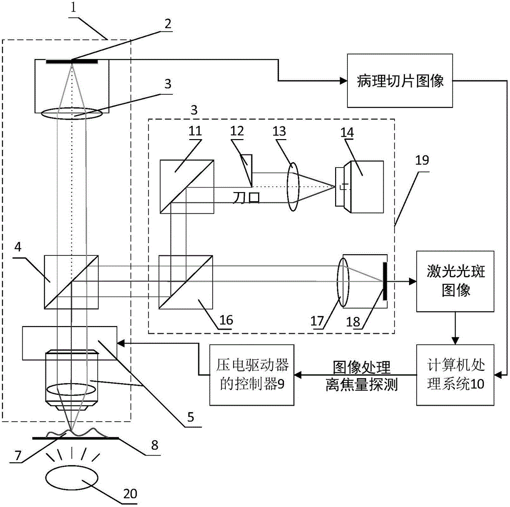
[0062] This embodiment provides an autofocus microscope based on the eccentric beam method and its focusing method.

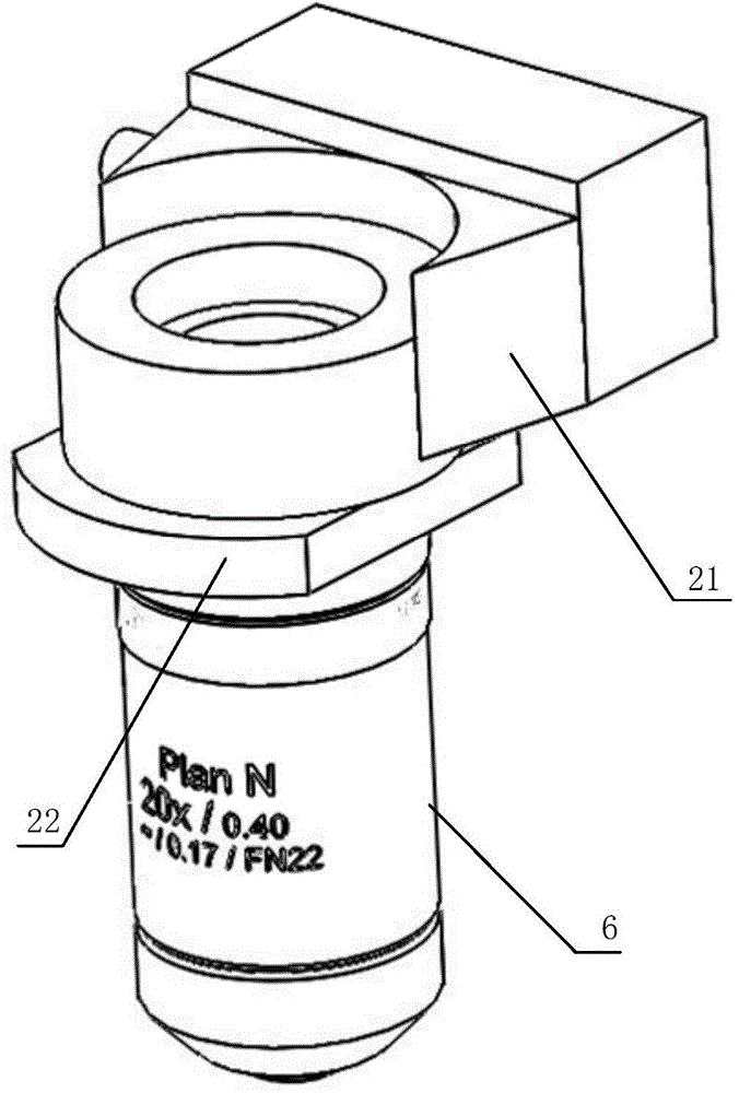
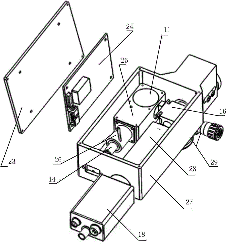
[0063] The autofocus microscope based on the eccentric beam method, its hardware composition includes an autofocus device and an XY stage, and the autofocus device includes an eccentric beam defocus detection module, a microscopic imaging module, and a piezoelectric objective lens driver; the eccentric The beam defocus detection module is used to emit an eccentric laser beam to irradiate the sample surface, and obtain the reflected semicircular spot image, and its radius is linearly related to the sample defocus; the XY stage is used to move the sample to realize the scanning movement of the sample; the microscopic imaging module is used to obtain a clear sample image after focusing; the piezoelectric objective lens driver is used to compensate the defocus amount of the current field of view to complete the focusing.

[0064] The autofocus device also includes ...


PUM


Abstract

The invention discloses an automatic focusing microscope based on an eccentric beam method and a focusing method thereof. The hardware comprises an eccentric beam defocus amount detection module, a microscopic imaging module, a piezo lens drive, an XY stage and a computer processing system. The defocus amount detection module transmits a semicircular laser beam to irradiate the surface of a sample and acquire a semicircular spot image formed by sample reflection. The computer processing system uses self-adaptive median filtering, Canny edge detection based on OSTU, the least square fitting and other algorithms to process the grayscaled spot image to acquire spot radius. According to a radius-defocus amount linear relationship model, the sample defocus amount in a field of vision can be calculated. The piezo lens drive drives a lens to compensate the defocus amount. After focusing, the microscopic imaging module acquires a clear sample image. The automatic focusing microscope based on the eccentric beam method and the focusing method thereof, which are provided by the invention, have the advantages of fast focusing speed, high focusing accuracy and large linear range, and can meet the requirement of fast and precise focusing of the microscope under a high power lens.

Description

technical field [0001] The invention relates to the technical field of microscope focusing, in particular to an autofocus device and method that uses an eccentric beam method as an optical path for defocus detection and cooperates with a spot image processing algorithm to calculate the defocus of a sample. Background technique [0002] The eccentric beam method is a typical microscope active focusing method, which is usually combined with the gray-scale center of gravity method to process the laser spot image to calculate the defocus amount of the sample. However, the gray-scale center-of-gravity method requires that the spot has good symmetry and uniform light intensity distribution, while the unevenness of the sample surface is very complicated, and the light intensity distribution of the light source is uneven, the second and third beam-splitting prisms have unsatisfactory light-splitting effects, and the Due to the diffraction of different samples and the difference in r...

Claims


Application Information

Patent Timeline
IPC IPC(8): G02B21/24G02B21/36
CPCG02B21/241G02B21/361G02B21/365
Inventor 谷朝臣李钦吴开杰胡洁关新平
Owner SHANGHAI JIAO TONG UNIV
Why Eureka
Eureka Blog
Learn More