Exhaust manifold for exhaust device of internal combustion engine
A technology of exhaust elbow and exhaust device, which is applied in the direction of exhaust device, exhaust treatment, noise reduction device, etc., can solve the problem of exhaust elbow weight and achieve the effect of reducing thermomechanical stress
- Summary
- Abstract
- Description
- Claims
- Application Information
AI Technical Summary
Problems solved by technology
Method used
Image
Examples
Embodiment Construction
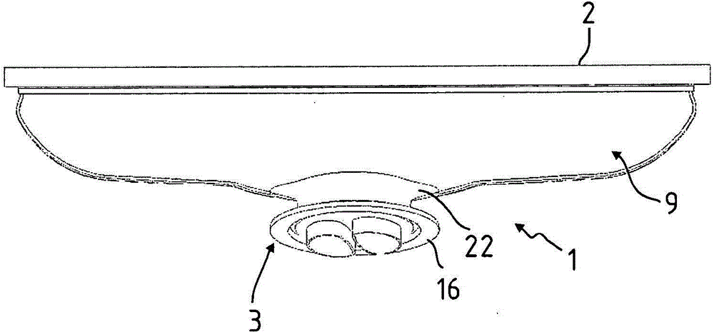
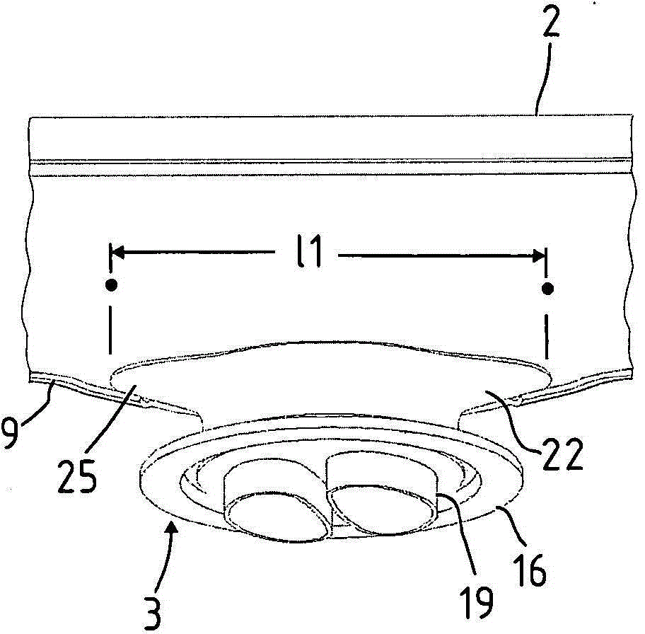
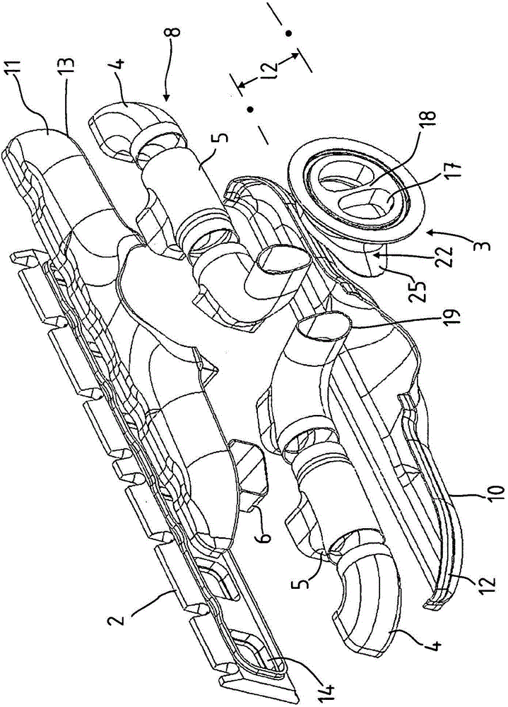
[0025] with the help of Figures 1 to 5 The illustration in the figure illustrates an exhaust manifold 1 according to the invention for an exhaust system of an internal combustion engine.
[0026] The exhaust manifold 1 has an inlet flange 2 and an outlet flange 3 , an inner pipe system 8 comprising a plurality of pipe parts 4 , 5 , 6 , 7 and a housing 9 surrounding the inner pipe system 8 at a distance. . The housing 9 consists of two shell parts 10 , 11 , a lower shell and an upper shell. The shell parts 10 , 11 are connected to one another at their overlapping edges 12 , 13 , in particular welded to one another.
[0027] Exhaust gases from the individual cylinders of the internal combustion engine pass through inlet openings 14 in the inlet flange 2 into the pipe pieces 4 , 5 , 6 , 7 . The exhaust gas is collected by the pipes 4 to 7 , redirected and fed to the outlet flange 3 . The inner tube system 8 is designed symmetrically about its vertical center axis. The pipe ...
PUM
 Abstract
Description
Claims
Application Information
 - R&D Engineer
- R&D Manager
- IP Professional
- Industry Leading Data Capabilities
- Powerful AI technology
- Patent DNA Extraction
Browse by: Latest US Patents, China's latest patents, Technical Efficacy Thesaurus, Application Domain, Technology Topic, Popular Technical Reports.
© 2024 PatSnap. All rights reserved.Legal|Privacy policy|Modern Slavery Act Transparency Statement|Sitemap|About US| Contact US: help@patsnap.com


