A Dielectrophoretic Particle Sorting Microfluidic Chip

A technology of microfluidic chip and dielectrophoresis, which is applied in the direction of laboratory equipment, laboratory containers, chemical instruments and methods, etc., can solve the problems of limited range of electrical signal amplitude and difficulty in flexible adjustment, and achieve low cost , proper layout and reasonable structure

Active Publication Date: 2016-06-08
HEBEI UNIV OF TECH
View PDF6 Cites 0 Cited by
  • Summary
  • Abstract
  • Description
  • Claims
  • Application Information

AI Technical Summary

Problems solved by technology

However, the adjustment of dielectrophoresis, the core technology of this method, is completed by an external signal generator. The purpose of blood cell separation is achieved by artificially adjusting the amplitude and frequency of the AC signal. The amplitude range of the electrical signal is limited by the signal generator. Its own characteristics, it is difficult to adjust flexibly

Method used


Image

  • A Dielectrophoretic Particle Sorting Microfluidic Chip
  • A Dielectrophoretic Particle Sorting Microfluidic Chip
  • A Dielectrophoretic Particle Sorting Microfluidic Chip

Examples


Embodiment 1

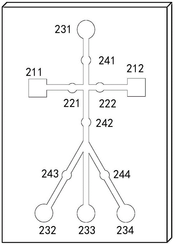
[0027] The first plating solution solenoid valve 321 and the second plating solution solenoid valve 322 are closed, all sorting solution solenoid valves are opened, and the solution containing dead and alive yeast cells is passed into the sorting solution inlet 231, and the dead and alive yeast cells are respectively subjected to Dielectrophoretic forces of different properties (positive or negative). Here, the width of the microchannel is 200um, the depth is 50um, the diameters of all the solenoid valve stations for the plating solution and the solenoid valve stations for the sorting solution are 3mm, and the vertical distance between the plating electrode and the plane electrode is 15um. Dead cells flow out from the first sorting solution outlet 232 and the third sorting solution outlet 234, corresponding to the weak electric field region; live cells flow out from the second sorting solution outlet 233, corresponding to the strong electric field region.

Embodiment 2

[0029] The first plating solution solenoid valve 321 and the second plating solution solenoid valve 322 are closed, all sorting solution solenoid valves are opened, and the human blood containing 1:50 dilution is passed into the sorting solution inlet 231, and red blood cells and white blood cells are respectively subjected to Dielectrophoretic forces of different properties (positive or negative). Here, the width of the microchannel is 120um, the depth is 60um, the diameters of all the solenoid valve stations for the plating solution and the solenoid valve stations for the sorting solution are 8mm, and the vertical distance between the plating electrode and the plane electrode is 20um. The red blood cells flow out from the first sorting solution outlet 232 and the third sorting solution outlet 234, corresponding to the weak electric field area; the white blood cells flow out from the second sorting solution sampling port 233, corresponding to the strong electric field area.

...


PUM


Abstract

The invention discloses a dielectrophoresis particle separation micro-fluidic chip. A micro-fluidic chip soft lithographic technique is used to acquire a micro-via and a micro-channel in certain shapes; by the aid of opening and closing of a plating solution electromagnetic valve, the inner wall of the micro-channel is locally gilded or slivered, forming a coating area; a coating electrode in the coating area and an electrified plane electrode form a closed non-uniform strong electric field area; variable electromagnetic force is applied over the coating electrode through a deformation control electromagnetic valve so as to cause deformation to the coating electrode, the electric field of the non-uniform strong electric field area changes in strength distribution, and electrophoretic force changes in distribution. By not adjusting an external signal source to change the amplitude of an external electric field but controlling the magnitude of the electromagnetic force of the deformation control electromagnetic valve, the field strength and electric field distribution of the non-uniform strong electric field area can be adjusted and dielectric particles different in property can be separated.

Description

technical field [0001] The invention relates to the technical field of particle sorting, in particular to a dielectrophoretic particle sorting microfluidic chip. Background technique [0002] Microfluidic chip technology integrates basic operating units such as sample preparation, pretreatment, reaction, separation, and detection in biological and chemical analysis processes into a micron-scale chip, which can realize the transportation and mixing of fluids, micro-nano particles, or droplets. , Sorting, enrichment, logic operations and other operations are of great strategic significance to the development of life sciences and information sciences. Under a non-uniform electric field, micro-nano-scale dielectric particles (such as polymer particles, various cells, bacteria, viruses, DNA, droplets, etc.) The areas of strongest or weakest aggregation are called positive dielectrophoretic (pDEP) and negative dielectrophoretic (nDEP) effects, respectively. This technology has t...

Claims


Application Information

Patent Timeline
Patent Type & Authority Patents(China)
IPC IPC(8): B01L3/00
Inventor 李姗姗闫姿姿李铭浩张明航戴士杰李铁军
Owner HEBEI UNIV OF TECH
Why Eureka
Try Eureka