Early cancer diagnosis device based on combination of auto-fluorescence lifetime imaging and fluorescence spectroscopy

A technology of autofluorescence and fluorescence spectroscopy, which is applied in the direction of fluorescence/phosphorescence, material excitation analysis, etc., can solve the problems of inability to reflect the differences in the microenvironment of the source, and achieve the effects of fast detection speed, convenient operation, and clear principle

Active Publication Date: 2015-09-02
FUDAN UNIV
View PDF4 Cites 17 Cited by
  • Summary
  • Abstract
  • Description
  • Claims
  • Application Information

AI Technical Summary

Problems solved by technology

Fluorescence spectrum can provide very important information, but it is only an averaged result, which cannot reflect the source of different fluorescent molecular substances in biological tissues or the microenvironmental differences of the same fluorescent molecule

Method used


Image

  • Early cancer diagnosis device based on combination of auto-fluorescence lifetime imaging and fluorescence spectroscopy
  • Early cancer diagnosis device based on combination of auto-fluorescence lifetime imaging and fluorescence spectroscopy
  • Early cancer diagnosis device based on combination of auto-fluorescence lifetime imaging and fluorescence spectroscopy

Examples


Embodiment 1

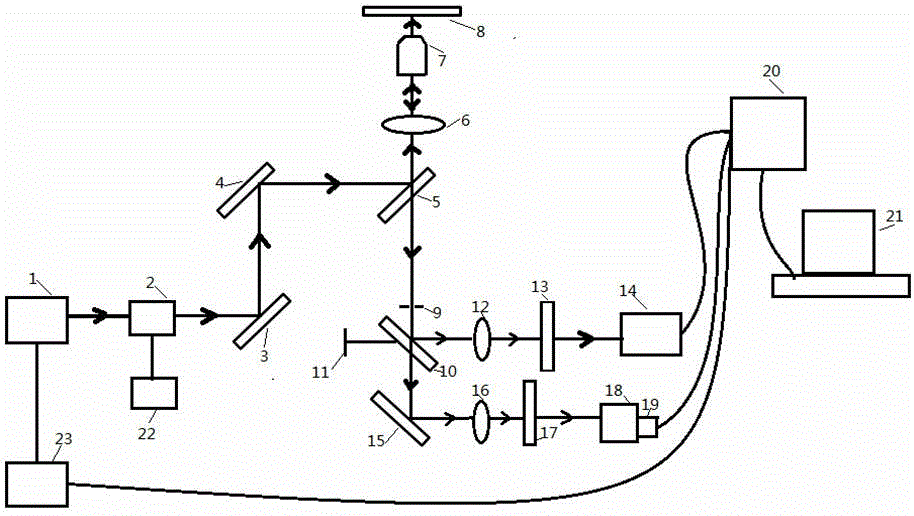
[0047] according to figure 1 with figure 2 As shown, a measurement device combining autofluorescence lifetime imaging and fluorescence spectrum of the present invention was made. First, the measurement of the autofluorescence lifetime imaging of the biological sample to be tested is carried out: the laser 1 emits picosecond pulsed laser or femtosecond pulsed laser; the laser emitted by the laser passes through two vibrating mirrors 2 in the XY direction to scan the XY plane; the excitation light passes through The reflection of the first reflection mirror 3 and the second reflection mirror 4 is adjusted to the dichroic mirror 5; the dichroic mirror 5 fully reflects the excitation light; the reflected excitation light enters the objective lens 7 through the convergence of the first converging lens group 6; the objective lens 7 will The converged light is focused on the tested biological sample; the autofluorescence emitted by the tested biological sample passes through the ob...

Embodiment 2

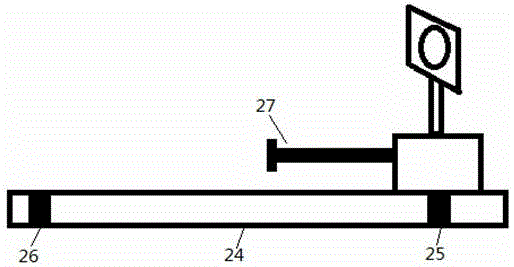
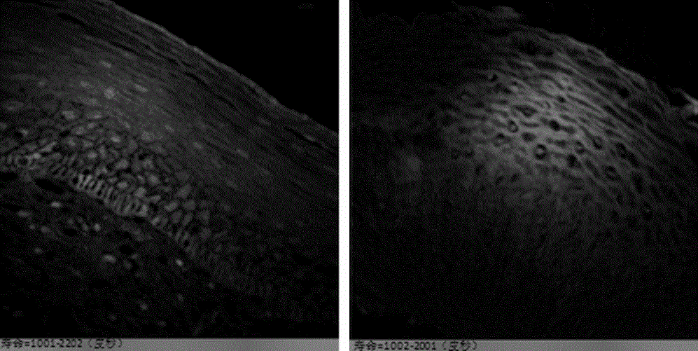
[0050] Implementation according to Example 1: First, the measurement of fluorescence lifetime imaging is performed on the epithelial region of human cervical tissue. Place the examined cervical tissue slice on the stage 8, and use a 60 times objective lens to observe the morphology of the epidermal cells of the cervical tissue. Advance the movable slider 11 to position 25, use picosecond pulsed laser light with a wavelength of 50 MHz and 405 nm to excite the fluorescent substance of the examined cervical tissue, the first color filter 13 and the second color filter in the fluorescence collection light path 17 are cut-off filters of 430 nm high pass. After the signal amplified by the photomultiplier tube 14 is processed by the host computer 20 equipped with a time-correlated single photon counter, the fluorescence lifetime is fitted by the fluorescence lifetime processing software and the result of obtaining the fluorescence lifetime image is as follows: image 3 shown.

[00...


PUM


Abstract

The invention belongs to the technical field of medical equipment, in particular to an early cancer diagnosis device based on combination of auto-fluorescence lifetime imaging and fluorescence spectroscopy. The auto-fluorescence lifetime imaging detection and fluorescence spectroscopy detection are coupled with a laser scanning confocal microscope for observing cytologic morphology of a biological sample. The device comprises a laser scanning confocal microscope device and two fluorescence signal acquisition devices; different detectors receive fluorescence lifetime information and fluorescence spectroscopy information respectively, and a computer processing system processes the auto-fluorescence lifetime information and fluorescence spectroscopy information. The multiple dimensional information of fluorescence images, fluorescence lifetime and fluorescence spectroscopy of the biological sample can be detected directly, early detection and diagnosis of various cancers can be implemented, and the application prospect is promised in the fields of biomedicine and clinical diagnostics.

Description

technical field [0001] The invention belongs to the technical field of medical equipment, and in particular relates to a device for early diagnosis of cancer. Background technique [0002] Optical diagnosis is an important part of biomedical photonics, which uses optical methods to examine and analyze diseases. The techniques of optical diagnosis can be divided into two categories: tissue spectral diagnosis and tissue optical imaging diagnosis. Laser-induced autofluorescence spectroscopy is an effective optical diagnostic method. Compared with normal tissues, the biomolecular components of human cancerous tissues are changed, so the fluorescence emitted is different. The use of laser-induced fluorescence spectroscopy is suitable for collecting data on metabolism or structure and function, so as to achieve the purpose of diagnosing cancer. The use of fluorescence spectroscopy technology can provide experimental basis for early diagnosis of cancer and provide reference for s...

Claims


Application Information

Patent Timeline
Patent Type & Authority Applications(China)
IPC IPC(8): G01N21/64
Inventor 糜岚王梦妍潘晓波宋川
Owner FUDAN UNIV
Why Eureka
Try Eureka