LED panel lamp with thermal conductive plastic frame free of substrate packaging

A technology of LED panel lights and thermally conductive plastics is applied in the parts of lighting devices, cooling/heating devices of lighting devices, optical elements for changing the spectral characteristics of emitted light, etc. Low thermal conductivity, hindering the dissipation of heat, etc., to achieve the effect of rich color, fewer parts and longer service life

Inactive Publication Date: 2015-09-02
SOUTH CHINA UNIV OF TECH
View PDF4 Cites 0 Cited by
  • Summary
  • Abstract
  • Description
  • Claims
  • Application Information

AI Technical Summary

Problems solved by technology

However, if the LED chip adopts the COB packaging method of the metal substrate, in order to prevent leakage, an insulating layer is usually added between the chip and the substrate. Because the thermal conductivity of the insulating layer material is very low, it will seriously hinder the heat dissipation and shorten the LED chip. Service life of LED panel light

Method used


Image

  • LED panel lamp with thermal conductive plastic frame free of substrate packaging
  • LED panel lamp with thermal conductive plastic frame free of substrate packaging
  • LED panel lamp with thermal conductive plastic frame free of substrate packaging

Examples


Embodiment

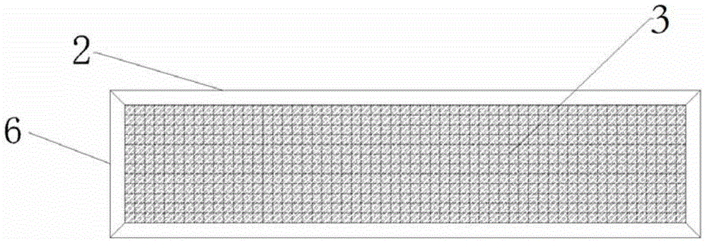
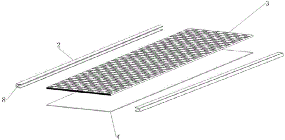
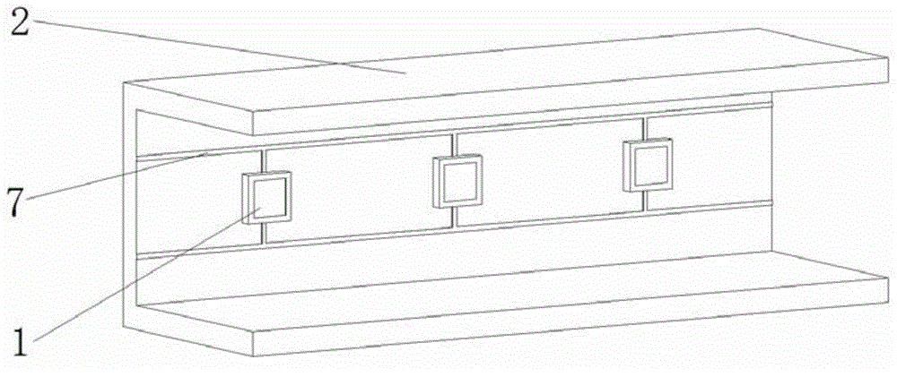
[0028] Such as Figure 1 to 5 As shown, this embodiment discloses an LED flat light packaged with a thermally conductive plastic frame without a substrate, which includes an LED chip 8, a back plate 4, a light guide plate 3, and a groove-shaped thermally conductive plastic frame 6, through which the thermally conductive plastic frame passes Set around the back plate 4 and the light guide plate 3, fixed and load-bearing the light guide plate 3 and the back plate 4 through the groove; the LED chip is packaged on the surface of the heat-conducting plastic frame groove through the COB packaging technology, as the edge light source of the LED flat light . In this embodiment, the light guide plate is an integrated integrated light guide plate, and the diffusion microstructure is integrated into the light guide plate, thereby eliminating the need for a diffusion film. In addition, the light guide plate is not attached to the side and back of the LED chip with a reflective film.

[002...


PUM


Abstract

The invention discloses an LED panel lamp with a thermal conductive plastic frame free of substrate packaging. The LED panel lamp comprises an LED chip, a back plate, a light guide plate and a groove type thermal conductive plastic frame used for bearing the back plate and the light guide plate. The thermal conductive plastic frame is arranged on the periphery of the back plate and the light guide plate through the groove. The LED chip is packaged in the surface of the thermal conductive plastic frame groove through the COB packaging technology to be used as a lateral entrance light source. According to the LED panel lamp, the light guide plate and the back plate are fixed and borne by the thermal conductive plastic frame, the LED chip is packaged in the surface of the thermal conductive plastic frame groove through the COB packaging technology, structures such as a substrate and an insulation layer are omitted, the number of contact interfaces between different materials is reduced, and therefore a radiating channel is greatly shortened; by means of the characteristic that thermal conductive plastic is low in thermal resistance and insulation, electric safety is ensured, and meanwhile the LED panel lamp radiating performance is greatly improved. The LED panel lamp has the advantages of being simple in structure, high in radiating efficiency and long in service life.

Description

Technical field [0001] The invention relates to an LED flat light, in particular to an LED flat light encapsulated by a thermally conductive plastic frame without a substrate. Background technique [0002] The flat panel light using LED as the light source has the advantages of green environmental protection, small size, long life, etc., making it more power-saving compared with other traditional light sources, and is more in line with the current trend of environmental protection, so it has a wide range of application prospects. However, limited by the current semiconductor manufacturing technology, the photoelectric conversion efficiency of the LED is only about 20%-30%, and the remaining energy will be converted into unusable heat energy, so there is a higher requirement for the heat dissipation performance of the lamp. [0003] At present, the traditional LED flat light has the following problems: The lamp beads of the lamp are mounted on the PCB board, and there are chips, die...

Claims


Application Information

Patent Timeline
IPC IPC(8): F21V29/87F21V23/00F21V9/16F21Y101/02
CPCF21V23/003F21V9/30
Inventor 文尚胜陈浩伟姚日晖马丙戌陈颖聪
Owner SOUTH CHINA UNIV OF TECH
Why Eureka
Try Eureka