
Work roll for cold rolling edge drop control and method for designing roll contour of work roll

A work roll and roll shape technology, applied in the direction of rolls, metal rolling, manufacturing tools, etc., can solve the problems of uneven force on the roll system, reduced grinding capacity of the grinder, and asymmetric control of the edge drop on both sides. , to avoid the easy peeling of the roll and the effect of good self-retention

Active Publication Date: 2015-09-02
UNIV OF SCI & TECH BEIJING
View PDF10 Cites 9 Cited by
  • Summary
  • Abstract
  • Description
  • Claims
  • Application Information

AI Technical Summary

Problems solved by technology

The Chinese patent with the publication number CN103949475 discloses a work roll that takes into account strip edge drop control and crown control. The full length of the roll body is designed as a three-section roll shape of a crown control section, an edge drop control section, and a straight line section. Good roll shape grinding performance can effectively control the edge drop, but it is mainly used in four-high rolling mills, and because the roll shape section participating in edge drop control is an arc curve, the slope of the curve roll is larger as it is closer to the edge , so it is easy to cause uneven stress on the roller system and serious asymmetry in the control of the edge drop on both sides when the strip steel runs off.
The Chinese patent with the publication number CN201231246 discloses a work roll for controlling the edge drop of strip steel. The circular arc and conical curve are ground on both sides of the flat roll work roll, and the intersection of the circular arc and the straight line is tangent. The main application The edge drop can be effectively controlled on the four-high rolling mill, but the roll shape will cause uneven stress on the roll system, asymmetric edge drop control, and unstable rolling when the strip runs off. The shape slope increases and decreases, the end portion of the roll shape may not be accurately ground on the grinding machine
The Chinese patent with the publication number CN101367092 discloses a work roll technology for controlling the edge drop of cold-rolled steel. The overall length of the work roll is designed as a special high-order curve. Effective control of edge drop, but this roll shape is only suitable for rolling mills where the work rolls cannot move and the rolling width specifications do not change frequently
The Chinese patent with the publication number CN102335675 discloses a roll shape at the end of the work roll that improves the edge drop control ability. It adopts a polynomial power function roll shape curve at the end of the work roll, which improves the work roll under a certain amount of movement. The ability to control the edge drop of the edge of the strip, but the slope of the roll-shaped edge changes greatly in the middle section, and it is easy to cause asymmetric control of the edge drop on both sides when the strip runs off. Large slope change and poor grinding performance
Document 1 (Single taper edge drop control of UCMW mill with parabolic function, 2009, Journal of University of Science and Technology Beijing) took a cold-rolled wide-band steel UCMW mill as the research object, and studied the influence of quadratic curve roll profile on edge drop control. The patent of shape and publication number CN102335675 has the problems of poor deviation resistance and poor grinding performance
[0003] To sum up, the above-mentioned 5 Chinese patents and document 1 introduce that the roll-shaped sections participating in the edge drop control are all high-order curves or sinusoidal curves, and the slope of the initial position of the roll-shaped section participating in the edge drop control is small. The ability to adjust the edge drop is insufficient, and the slope of the roll shape is larger when it is closer to the edge. When it is used for production, the stress value of the edge area of ​​the strip is relatively large. more likely to happen

Method used


Image

  • Work roll for cold rolling edge drop control and method for designing roll contour of work roll
  • Work roll for cold rolling edge drop control and method for designing roll contour of work roll
  • Work roll for cold rolling edge drop control and method for designing roll contour of work roll

Examples


Embodiment

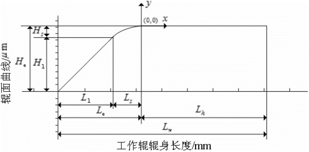
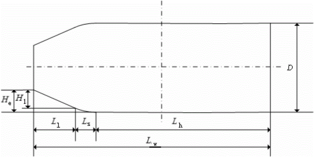
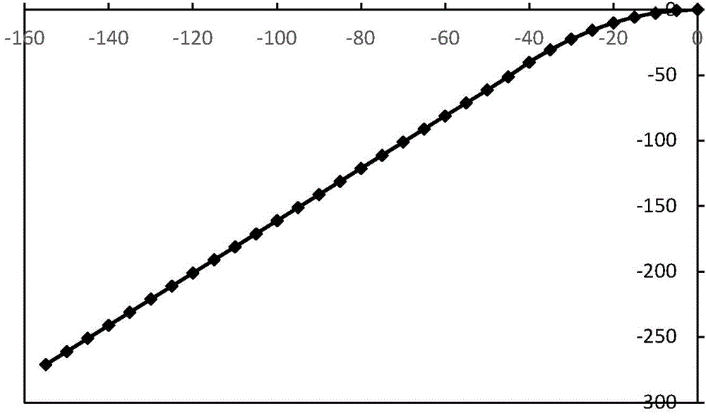
[0067] See attached figure 1 , in the two-dimensional coordinate system in the figure, the roll shape of the work roll used for cold rolling edge drop control provided by the embodiment of the present invention includes an oblique straight line segment, a quadratic curve segment and a horizontal straight line segment, and the quadratic curve segment is at its two ends They are respectively tangent to the oblique straight line segment and the horizontal straight line segment, and the roll curve equation is:

[0068] y ( x ) = 2 x + 40 - 155 ≤ x - 40 - ...


PUM


Abstract

The invention discloses a work roll for cold rolling edge drop control and a method for designing a roll contour of the work roll. The roll contour of the work roll comprises an oblique line section, a quadratic curve section and a horizontal line section. Two ends of a quadratic curve are respectively tangential to a horizontal line and an oblique line, the roll contour of an end of a side of the work roll is formed by the quadratic curve and the oblique line and participates in edge drop control, the quadratic curve section is short but is high in taper, and the oblique line section is long. The work roll and the method have the advantages that the edge drop control ability of integral edge regions can be guaranteed; regions of the edges of band steel are low in stress value, and accordingly the possibility of band breakage can be reduced; starting positions of the edges of the band steel are in smooth transition, so that stress concentration can be prevented, and the self-preservation property of the shape of the roll can be improved; the probability of band breakage due to deviation of the band steel and excessively high stress at the edges of each single side of the band steel can be reduced, and accordingly the work roll is excellent in deviation resistance; the roll contour is excellent in grinding performance, and the surface quality of the ends of the roll can be guaranteed in grinding procedures.

Description

technical field [0001] The invention relates to the technical field of steel rolling, in particular to a work roll and a roll shape design method for edge drop control in cold rolling. Background technique [0002] Cold rolling edge drop control technology is a key technology for the production of silicon steel and tin-plated substrates. At present, there are many cold rolling edge drop control technologies, among which the work roll shape technology is the most simple and effective control method. The drop control ability is slightly insufficient, or the anti-deviation ability is weak, or the grinding performance is poor, or there is stress concentration, and there are still many deficiencies. The T-WRS technology of Kawasaki Iron and Steel Co., Ltd. adopts work rolls with a linear taper at one end, which are anti-symmetrically arranged on the upper and lower work rolls, and controls the edge drop of the strip by moving the work rolls axially. However, the T-WRS shape The...

Claims


Application Information

Patent Timeline
IPC IPC(8): B21B27/02
Inventor 王晓晨杨荃孙友昭梁治国何飞马粹
Owner UNIV OF SCI & TECH BEIJING
Learn More