
Detection robot based on negative pressure adsorption

A robot and negative pressure technology, applied in motor vehicles, optical testing flaws/defects, transportation and packaging, etc., can solve problems such as manual safety hazards, low work efficiency, and heavy inspection workload, so as to reduce inspection costs and improve work Efficiency and the effect of eliminating potential safety hazards

Active Publication Date: 2015-08-26
MAANSHAN JULI SCI & TECH
View PDF7 Cites 5 Cited by
  • Summary
  • Abstract
  • Description
  • Claims
  • Application Information

AI Technical Summary

Problems solved by technology

[0002] At present, if the bridge bottom fracture detection team detects manually, but the bridge bottom cannot be reached manually, so it can only be detected by using high-magnification telescopes or by setting up scaffolding detection platforms. High-magnification telescopes are easy to miss small cracks when detecting small cracks. The detection platform is set up. It requires a lot of manpower and material resources, and the construction site of the platform is complicated, the construction is difficult, the inspection workload is heavy, the work efficiency is low, and there are safety hazards in manual walking on the inspection platform
The current patent name is a negative pressure adsorption climbing robot for detecting bridge cracks, application number: 201310143474.7, using rubber sealing skirt and negative pressure technology to realize the adsorption of the detection robot and the bottom wall of the bridge, which cannot be detected in key detection parts Staying for a long time, work consumes a lot of energy

Method used


Image

  • Detection robot based on negative pressure adsorption
  • Detection robot based on negative pressure adsorption
  • Detection robot based on negative pressure adsorption

Examples


Embodiment Construction

[0022] The present invention will be further described below in conjunction with the accompanying drawings.

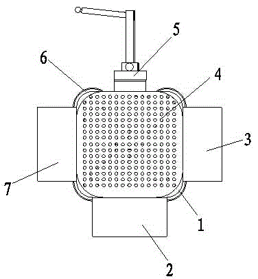
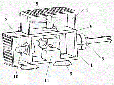
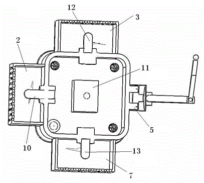
[0023] Such as figure 1 As shown, a detection robot based on negative pressure adsorption of the present invention, the robot system includes a robot shell 1, a propulsion system 2, a left adjustment system 3, a positive pressure system 4, a detection system 5, an adsorption suction cup 6, and a right adjustment system 7. The control system 11, the robot shell 1 is provided with a positive pressure system 4, and the positive pressure system 4 will pass the robot positive pressure centrifugal fan 8 to make the detection robot close to the bottom of the bridge; the left and right sides of the robot shell 1 are respectively set There are left adjustment system 3 and right adjustment system 7, left adjustment system 3 and right adjustment system 7, when the robot needs to turn, adjust the speed of left centrifugal fan 12 and right centrifugal fan 13 to detect the left and ...


PUM


Abstract

The invention discloses a detection robot based on negative pressure adsorption. The detection robot comprises a robot shell, a propelling system, a left adjusting system, a left pressure system, a detection system, an adsorption suction cup, a right adjusting system and a control system. A positive pressure system is arranged on the robot shell, and the left adjusting system and the right adjusting system are arranged on the left side and the right side of the robot shell respectively; the propelling system is arranged on the rear side of the robot shell, and the detection system is arranged at the front end of the robot shell; and the adsorption suction cup is arranged at the lower end of the robot shell. The detection robot has the advantages that the detection system has no blind angle within 360 degrees, the detection range is large, and through a wireless system, picture detection visualized analysis is achieved, and the subjective effect in the manual detection is avoided; through the negative pressure system, the suction cup carries out adsorption so as to enable the robot to stay on the main detection portion for a long time; a detection platform is not needed to be erected in the detection work process, the detection cost is reduced, and potential safety hazards of aloft work are eliminated.

Description

technical field [0001] The invention relates to the technical field of unmanned detection of bridge bottom fracture detection, in particular to a detection robot based on negative pressure adsorption. Background technique [0002] At present, if the bridge bottom fracture detection team detects manually, but the bridge bottom cannot be reached manually, so it can only be detected by using high-magnification telescopes or by setting up scaffolding detection platforms. High-magnification telescopes are easy to miss small cracks when detecting small cracks. The detection platform is set up. It requires a lot of manpower and material resources, and the construction site of the platform is complex, the construction is difficult, the inspection workload is heavy, the work efficiency is low, and there are safety hazards in manually walking on the inspection platform. The current patent name is a negative pressure adsorption climbing robot for detecting bridge cracks, application nu...

Claims


Application Information

Patent Timeline
IPC IPC(8): B62D57/024G01N21/88
Inventor 温从众
Owner MAANSHAN JULI SCI & TECH
Learn More