Metal mask plate structure and manufacturing method thereof

The technology of a metal mask plate and a manufacturing method is applied in the direction of metal material coating process, ion implantation plating, coating, etc., and can solve the problems of difficult control of metal mesh plate precision, increased manufacturing process difficulty, increased manufacturing cost, and the like, Achieve the effect of good production practical value, diversify risks, and improve production accuracy

Inactive Publication Date: 2015-08-19
TRULY HUIZHOU SMART DISPLAY
View PDF4 Cites 13 Cited by
  • Summary
  • Abstract
  • Description
  • Claims
  • Application Information

AI Technical Summary

Problems solved by technology

[0004] like Figure 1-2 As shown, the metal mask corresponding to the existing large-size substrate mostly adopts a divided metal mesh, and the divided metal mesh 01 forms a narrow and long strip shape. As the size of the substrate increases, the divided metal mesh The length of 01 is also increasing, and the increase in length and size will lead to an increase in manufacturing costs, and the difficulty of the manufacturing process will also increase, and the accuracy of the metal mesh is also difficult to control. , the entire segmented metal mesh panels are scrapped

Method used


Image

  • Metal mask plate structure and manufacturing method thereof
  • Metal mask plate structure and manufacturing method thereof
  • Metal mask plate structure and manufacturing method thereof

Examples


Embodiment 1

[0025] Please refer to Figure 3-5 , Embodiment 1 of the present invention includes:

[0026] A metal mask structure, comprising a mask frame 4, divided into three sub-metal mesh panels with different areas, respectively sub-metal mesh panel 1, sub-metal mesh panel 2, sub-metal mesh panel 3, sub-metal mesh panel The stencil 1, the sub-metal stencil 2, and the sub-metal stencil 3 are spliced ​​into a complete metal stencil.

[0027] In the first embodiment, the sub-metal mesh panel 1 , the sub-metal mesh panel 2 and the sub-metal mesh panel 3 are spliced ​​into a complete metal mesh panel by welding.

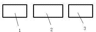
[0028] Sub-metal mesh panel 1, sub-metal mesh panel 2, and sub-metal mesh panel 3 are three rectangular panels with equal width and incomplete length, and these three rectangular panels are arranged in sequence based on sides of equal width, as shown in image 3 shown.

[0029] A method for manufacturing a metal mask structure, comprising 3 steps; step 1, providing the aforeme...

Embodiment 2

[0035] Embodiment 2 of the present invention includes:

[0036] A metal mask structure includes a mask frame, which is divided into four sub-metal mesh panels with equal areas, and the four sub-metal mesh panels are spliced ​​to form a complete metal mesh panel.

[0037] In the second embodiment, 4 sub-metal mesh panels are spliced ​​into a complete metal mesh panel by means of hinge joints.

[0038] The 4 sub metal mesh panels are 4 rectangular panels with equal length, width and thickness.

[0039] A method for manufacturing a metal mask structure, comprising 3 steps; step 1, providing the aforementioned 4 sub-metal mesh panels and a mask frame for carrying the sub-metal mesh; the mask frame is provided with a Fixing position of sub-metal mesh panels; step 2, splicing 4 sub-metal mesh panels into a complete metal mesh panel by means of hinges; step 3, hinge-fixing the spliced ​​metal mesh panels on the mask frame superior.

[0040]In the step 2, the 4 sub-metal mesh panel...


PUM


Abstract

The invention discloses a metal mask plate structure. The metal mask plate structure comprises a plurality of divided daughter mask plates with equal or unequal areas, wherein the plurality of daughter mask plates can form a complete mask plate through splicing. The invention also discloses a manufacturing method for the metal mask plate. The manufacturing method comprises the following steps: step 1, providing a mask plate frame used for bearing the daughter mask plates and the above-mentioned plurality of daughter mask plates, wherein the mask plate frame is provided with fixed position clips used for fixing the daughter mask plates; step 2, placing the plurality of daughter mask plates on the fixed position clips on the mask plate frame and fixing the daughter mask plates via the fixed position clips; and step 3, splicing the plurality of daughter mask plates into a complete mask plate through welding or hinging. According to the metal mask plate structure provided by the invention, a segmented mask plate can be further divided into a plurality of daughter mask plates, so manufacturing difficulty of the mask plate can be abated, manufacturing cost for the mask plate can be reduced, the risk of scrapping of the whole mask plate can be lowered down, the recycle life of the mask plate can be prolonged, and manufacturing precision of each segment of the mask plate can be improved.

Description

technical field [0001] The invention relates to the field of OLED production, in particular to a metal mask structure and a manufacturing method thereof. Background technique [0002] Organic Light-Emitting Diodes (OLED for short) are self-luminous devices that do not require a backlight source and are light and thin in appearance, while traditional liquid crystal displays (LCDs) require a backlight source to work and have a thicker appearance. Organic light-emitting diode displays have low power consumption, wide viewing angles, and fast screen response, which is the technology that best meets people's future functional requirements for displays. Therefore, organic light-emitting diodes are expected to replace liquid crystal displays in the near future and have high market potential. [0003] In the production process of organic small molecule light-emitting diodes, the current relatively mature technology is the use of vacuum evaporation technology. During the device prep...

Claims


Application Information

Patent Timeline
IPC IPC(8): C23C14/04
Inventor 苏君海柯贤军吴俊雄冉应刚马得贵李建华
Owner TRULY HUIZHOU SMART DISPLAY
Why Eureka
Try Eureka